AUTOMATIC TRANSMISSION SYSTEM (for 1KD-FTV), Diagnostic DTC:P0500

| DTC Code | DTC Name |
|---|---|
| P0500 | Vehicle Speed Sensor Malfunction |
DESCRIPTION
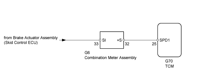
The speed sensor detects the wheel speed and sends the appropriate signals to the skid control ECU. The skid control ECU converts these wheel speed signals into a pulse signal and outputs it to the TCM via the combination meter. The TCM determines the vehicle speed based on the frequency of this pulse signal.
| DTC Code | DTC Detection Condition | Trouble Area |
|---|---|---|
| P0500 | While the vehicle is being driven, no vehicle speed sensor signal is transmitted to the TCM (2-trip detection logic). |
|
MONITOR DESCRIPTION
The TCM assumes that the vehicle is being driven when the indicated vehicle speed is more than 9 km/h (5.6 mph). If there is no speed signal from the combination meter despite this condition being met, the TCM interprets this as a malfunction in the speed signal circuit. The TCM then illuminates the MIL and stores the DTC.
WIRING DIAGRAM
INSPECTION PROCEDURE
PROCEDURE
-
READ VALUE USING INTELLIGENT TESTER (VEHICLE SPEED)
-
Drive the vehicle and check whether the operation of the speedometer in the combination meter assembly is normal.
Tech Tips
-
The vehicle speed sensor is operating normally if the speedometer reading is normal.
-
If the speedometer does not operate, check it by following the procedure described for a speedometer malfunction.
-
-
Connect the intelligent tester to the DLC3.
-
Turn the ignition switch to ON.
-
Turn the intelligent tester on.
-
Enter the following menus: Powertrain / ECT / Data List.
-
Drive the vehicle.
-
Read the value displayed on the tester.
ECT Tester Display Measurement Item/Range Normal Condition Diagnostic Note Vehicle Speed Vehicle speed/
Min.: 0 km/h (0 mph)
Max.: 255 km/h (158 mph)
Actual vehicle speed - OK Vehicle speed displayed on tester and speedometer display are equal.
NG 
CHECK COMBINATION METER ASSEMBLY (SPD SIGNAL WAVEFORM) Click here
OK 
CHECK FOR INTERMITTENT PROBLEMS Click here
-
-
CHECK COMBINATION METER ASSEMBLY (SPD SIGNAL WAVEFORM)
-
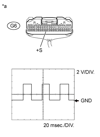
Text in Illustration *a Component with harness connected
(Combination Meter Assembly)
Remove the combination meter assembly with the connector(s) still connected.
-
Move the shift lever to N.
-
Jack up the vehicle.
-
Turn the ignition switch to ON.
-
Check the signal waveform according to the condition(s) in the table below.
Measurement Condition Terminal No. (Symbol) Tool Setting Condition G6-32 (+S) - Body ground 2 V/DIV., 20 msec./DIV. Vehicle speed 20 km/h (12 mph) OK The waveform is displayed as shown in the illustration.
NG 
CHECK METER / GAUGE SYSTEM (SPEED SIGNAL CIRCUIT) Click here
OK 
-
-
CHECK HARNESS AND CONNECTOR (COMBINATION METER ASSEMBLY - TCM)
-
Disconnect the G6 combination meter assembly connector.
-
Disconnect the G70 TCM connector.
-
Measure the resistance according to the value(s) in the table below.
Standard Resistance Tester Connection Condition Specified Condition G6-32 (+S) - G70-25 (SPD1) Always Below 1 Ω G6-32 (+S) or G70-25 (SPD1) - Body ground Always 10 kΩ or higher
NG
REPAIR OR REPLACE HARNESS OR CONNECTOR
OK
REPLACE TCM Click here
-