AUTOMATIC TRANSMISSION SYSTEM, Diagnostic DTC:P2759

| DTC Code | DTC Name |
|---|---|
| P2759 | Torque Converter Clutch Pressure Control Solenoid Control Circuit Electrical (Shift Solenoid Valve SLU) |
DESCRIPTION
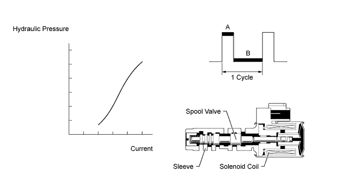
The amount of current flow to the solenoid is controlled by the duty ratio* of the ECM output signal. During the lock-up operation, if the duty ratio increases, the lock-up hydraulic pressure increases.
Tech Tips
*: The duty ratio is the ratio of the current ON time (A) to the total of the current ON and OFF time (A + B).
Duty Ratio (%) = A / (A + B) x 100
| DTC Code | DTC Detection Condition | Trouble Area |
|---|---|---|
| P2759 | Open or short is detected in the shift solenoid valve SLU circuit for 1 second or more while driving (1-trip detection logic). |
|
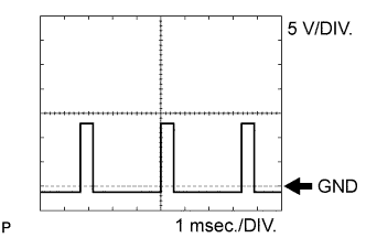
Reference: Inspect using an oscilloscope.
Check the waveform of the ECM connector.
| Standard | ||||||||
|---|---|---|---|---|---|---|---|---|
|
MONITOR DESCRIPTION
When an open or short in the shift solenoid valve SLU circuit is detected, the ECM determines that there is a malfunction. The ECM will illuminate the MIL and store the DTC.
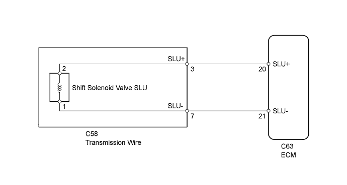
WIRING DIAGRAM
INSPECTION PROCEDURE
PROCEDURE
-
INSPECT TRANSMISSION WIRE (SHIFT SOLENOID VALVE SLU)
-
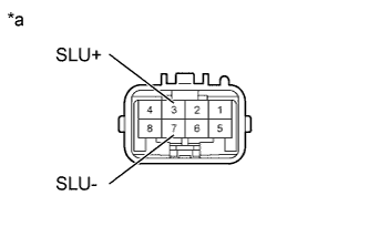
Text in Illustration *a Component without harness connected
(Transmission Wire)
Disconnect the C58 transmission wire connector.
-
Measure the resistance according to the value(s) in the table below.
Standard Resistance Tester Connection Condition Specified Condition 3 (SLU+) - 7 (SLU-) 20°C (68°F) 5.1 to 5.5 Ω 3 (SLU+) - Body ground Always 10 kΩ or higher 7 (SLU-) - Body ground Always 10 kΩ or higher
NG 
OK 
-
-
CHECK HARNESS AND CONNECTOR (TRANSMISSION WIRE - ECM)
-
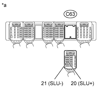
Text in Illustration *a Rear view of wire harness connector
(to ECM)
Disconnect the C63 ECM connector.
-
Measure the resistance according to the value(s) in the table below.
Standard Resistance Tester Connection Condition Specified Condition C63-20 (SLU+) - C63-21 (SLU-) 20°C (68°F) 5.1 to 5.5 Ω C63-20 (SLU+) - Body ground Always 10 kΩ or higher C63-21 (SLU-) - Body ground Always 10 kΩ or higher
NG 
REPAIR OR REPLACE HARNESS OR CONNECTOR
OK 
REPLACE ECM Click here
-
-
INSPECT SHIFT SOLENOID VALVE SLU
-
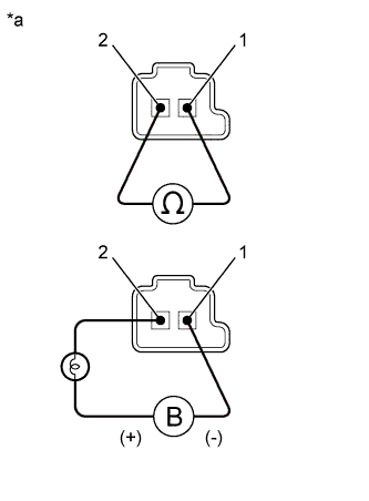
Text in Illustration *a Component without harness connected
(Shift Solenoid Valve SLU)
Remove shift solenoid valve SLU.
-
Measure the resistance according to the value(s) in the table below.
Standard Resistance Tester Connection Condition Specified Condition 1 - 2 20°C (68°F) 5.1 to 5.5 Ω -
Apply 12 V battery voltage to the shift solenoid valve and check that the valve moves and makes an operating noise.
OK Measurement Condition Specified Condition
-
Battery positive (+) with a 21 W bulb → Terminal 2
-
Battery negative (-) → Terminal 1
Valve moves and makes an operating noise -
NG
REPLACE SHIFT SOLENOID VALVE SLU Click here
OK
REPAIR OR REPLACE TRANSMISSION WIRE Click here
-