AUTOMATIC TRANSMISSION UNIT REASSEMBLY

-
BEARING POSITION
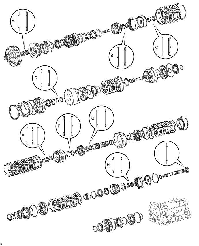
Bearing Diameter Mark Front Race Diameter
Inside/Outside
Thrust Bearing Diameter
Inside/Outside
Rear Race Diameter
Inside/Outside
A 28.45 mm (1.12 in.)/29.9 to 30.1 mm (1.18 to 1.19 in.) 29.0 to 29.25 mm (1.14 to 1.15 in.)/50.04 to 50.34 mm (1.97 to 1.98 in.) - B 33.0 to 33.25 mm (1.30 to 1.31 in.)/49.9 to 50.4 mm (1.96 to 1.98 in.) 31.45 to 31.70 mm (1.24 to 1.25 in.)/49.1 to 49.4 mm (1.93 to 1.94 in.) - C 37.1 to 37.3 mm (1.46 to 1.47 in.)/58.70 to 58.95 mm (2.31 to 2.32 in.) 33.75 to 33.85 mm (1.329 to 1.333 in.)/49.8 to 50.3 mm (1.96 to 1.98 in.) - D 36.5 to 37 mm (1.44 to 1.46 in.)/50.75 to 50.95 mm (2.00 to 2.01 in.) 33.55 to 33.80 mm (1.32 to 1.33 in.)/47.62 to 47.87 mm (1.87 to 1.88 in.) - E 25.98 mm (1.02 in.)/48.87 mm (1.92 in.) 25.94 to 26.07 mm (1.02 to 1.03 in.)/46.62 to 46.87 mm (1.84 to 1.85 in.) 26.5 to 27.0 mm (1.04 to 1.06 in.)/47.02 mm (1.85 in.) F - 35 to 35.3 mm (1.38 to 1.39 in.)/50.50 to 53.75 mm (2.11 to 2.12 in.) 34 to 34.5 mm (1.34 to 1.36 in.)/48.5 to 49 mm (1.91 to 1.93 in.) G 33.55 to 33.80 mm (1.32 to 1.33 in.)/47.3 to 47.8 mm (1.86 to 1.88 in.) 35.45 to 35.61 mm (1.396 to 1.402 in.)/47.62 to 47.87 mm (1.87 to 1.88 in.) - H 28.5 mm (1.12 in.)/44.2 mm (1.74 in.) 28.5 mm (1.12 in.)/44.2 mm (1.74 in.) - I - 39.38 mm (1.55 in.)/57.94 to 58.36 mm (2.28 to 2.30 in.) - -
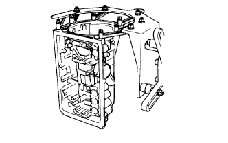
FIX TRANSMISSION CASE
-
Install the transmission case to an overhaul attachment.
-
-
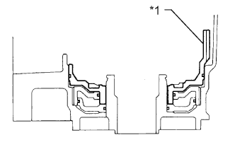
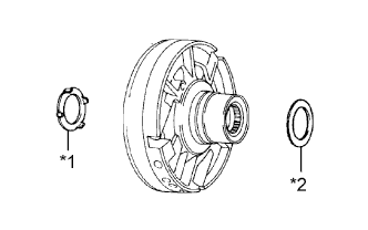
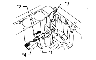
INSTALL NO. 1 FIRST AND REVERSE BRAKE PISTON
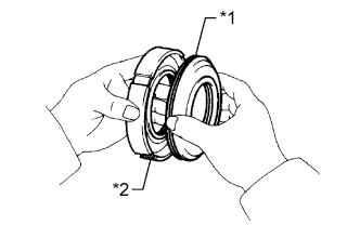
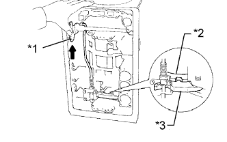
Text in Illustration *1 No. 1 First and Reverse Brake Piston *2 Reaction Sleeve
-
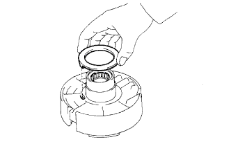
Coat 2 new O-rings with ATF and install them to the No. 1 brake piston.
-
Coat a new O-ring with ATF and install it to the reaction sleeve.
-
Install the No. 1 brake piston to the reaction sleeve.
-
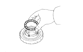
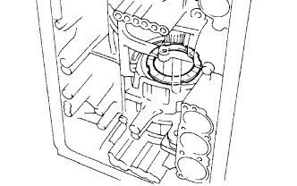
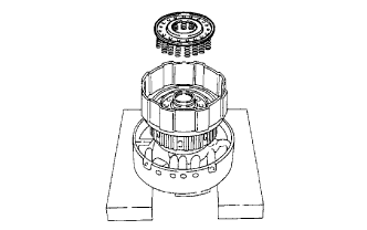
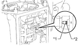
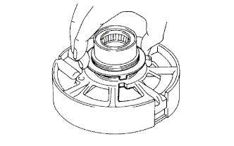
Text in Illustration *1 No. 1 First and Reverse Brake Piston *2 Reaction Sleeve With the No. 1 brake piston underneath (the rear side), install the brake reaction sleeve and No. 1 brake piston to the transmission case.
Note
Be careful not to damage the O-rings.
-
-
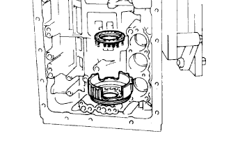
INSTALL NO. 2 FIRST AND REVERSE BRAKE PISTON
-
Coat a new O-ring with ATF and install it to the brake piston.
-
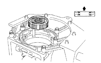
Text in Illustration *1 No. 2 First and Reverse Brake Piston With the spring seat of the piston facing upward (the front side), install the piston to the transmission case.
Note
Be careful not to damage the O-ring.
-
-
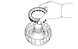
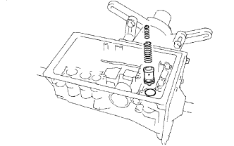
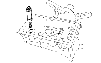
INSTALL FIRST AND REVERSE BRAKE RETURN SPRING SUB-ASSEMBLY
-
Install the No. 2 brake return spring to the brake piston.
-
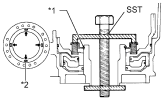
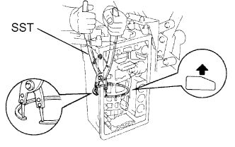
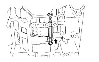
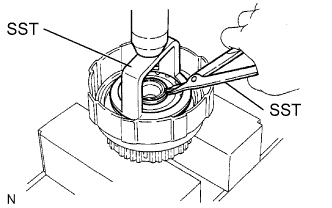
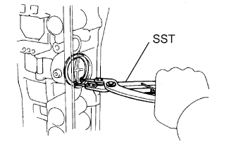
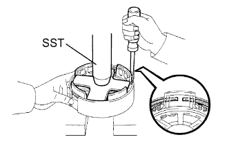
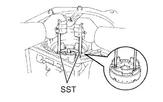
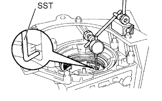
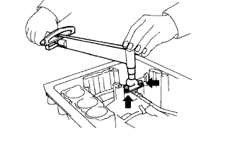
Place SST on the brake return spring and compress the brake return spring.
- SST
- 09350-30020 ( 09350-07050 )
-
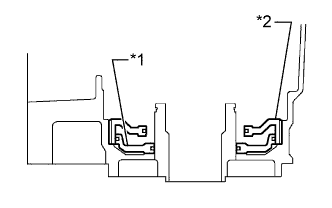
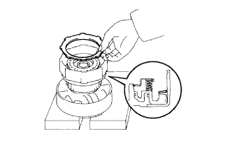
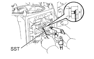
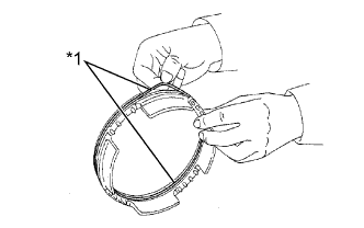
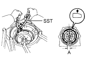
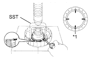
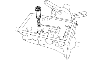
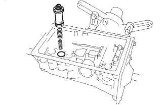
Using SST, install the snap ring. Make sure the end gap of the snap ring is not aligned with a spring retainer claw.
- SST
- 09350-30020 ( 09350-07070 )
Text in Illustration *1 Snap Ring *2 Retainer Claw
-
-
INSPECT PISTON OPERATION OF FIRST AND REVERSE BRAKE
-
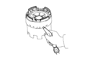
Make sure the first and reverse brake pistons move smoothly when compressed air is applied to the transmission case.
-
-
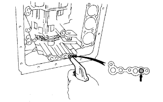
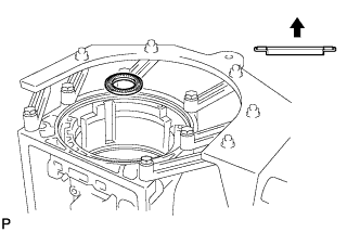
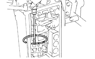
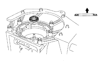
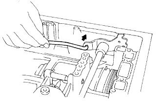
INSTALL LEAF SPRING
-
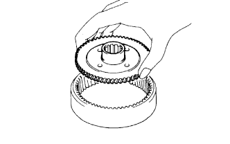
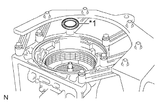
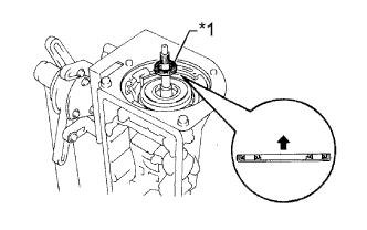
INSTALL REAR PLANETARY RING GEAR FLANGE
-
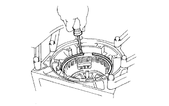
Install the ring gear flange to the rear planetary ring gear.
-
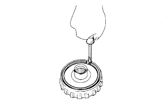
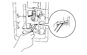
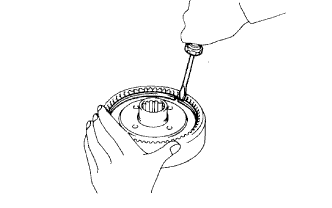
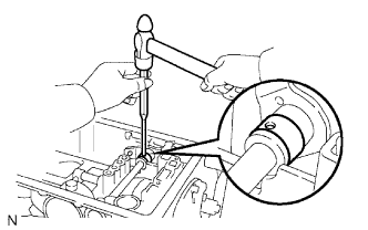
Using a screwdriver, install the snap ring.
-
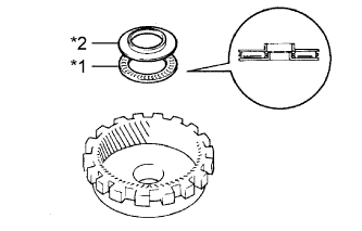
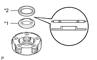
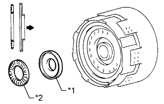
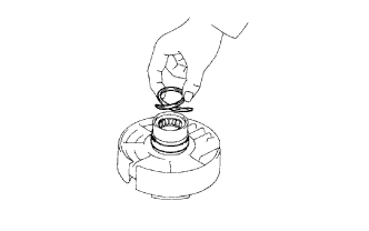
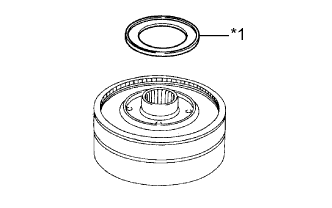
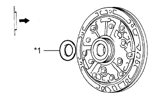
Text in Illustration *1 Bearing H *2 Bearing Race H Coat the bearing and bearing race with petroleum jelly and install them to the rear planetary ring gear.
Races and Bearing Diameter Item Inside Outside Bearing H 28.5 mm (1.12 in.) 44.2 mm (1.74 in.) Bearing Race H 28.5 mm (1.12 in.) 44.2 mm (1.74 in.) -
Coat the No. 2 planetary carrier thrust washer with petroleum jelly.
-
Install the thrust washer to both sides of the planetary gear.
Tech Tips
Make sure that the tabs of the washer fit into the cutout portions of the planetary gear.
-
-
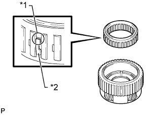
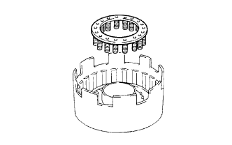
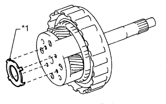
INSTALL NO. 2 1-WAY CLUTCH
-
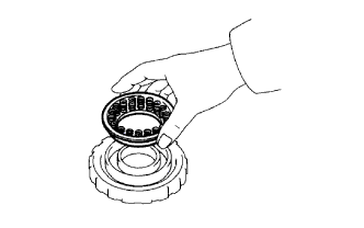
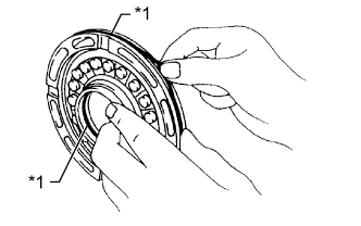
Install the 1-way clutch to the planetary gear.
Tech Tips
Make sure that the open ends of the guides of the 1-way clutch are facing upward.
Text in Illustration *1 Open End *2 Guide -
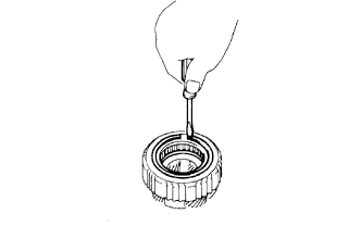
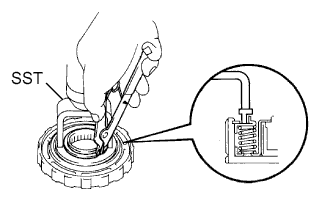
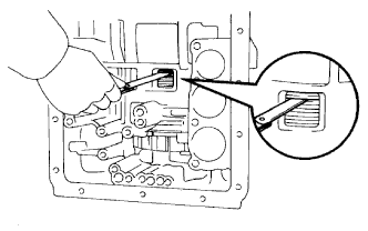
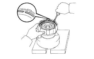
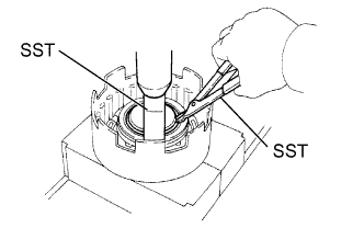
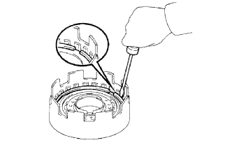
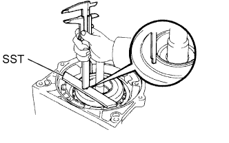
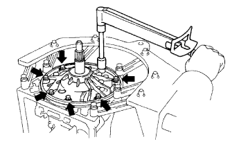
Using a screwdriver, install the snap ring.
-
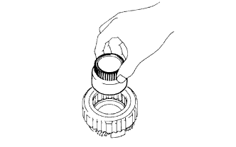
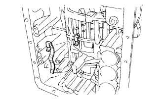
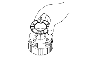
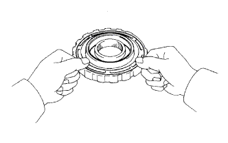
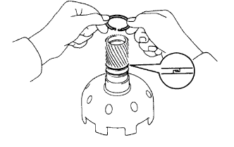
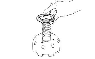
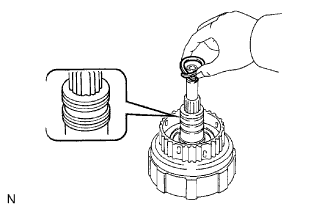
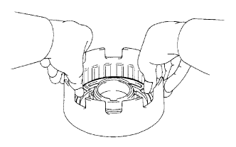
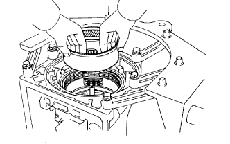
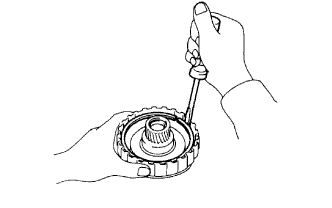
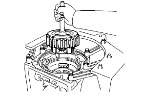
While turning the 1-way clutch inner race counterclockwise, install the 1-way clutch inner race to the planetary gear.
-
-
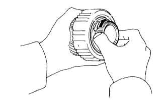
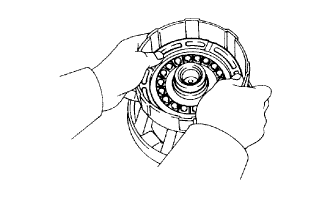
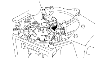
INSPECT NO. 2 1-WAY CLUTCH
-
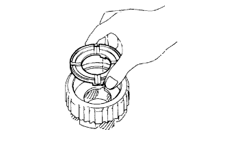
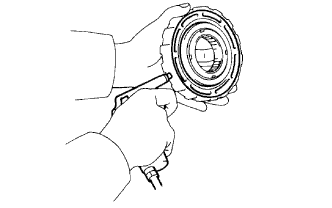
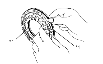
Hold the planetary gear and turn the 1-way clutch inner race. Check that the 1-way clutch inner race can be turned counterclockwise freely and locks when turned clockwise.
Text in Illustration 
Lock 
Free
-
-
INSTALL REAR PLANETARY GEAR ASSEMBLY
-
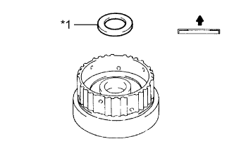
Coat the No. 1 planetary carrier thrust washer with petroleum jelly.
-
Install the thrust washer to the planetary gear.
Tech Tips
Make sure that the tabs of the washer fit to the cutout portions of the planetary gear.
-
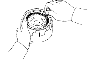
Install the rear planetary gear to the rear planetary ring gear.
-
-
INSTALL PLANETARY OUTPUT SHAFT OIL SEAL RING
-
Coat the oil seal ring with ATF and install it to the output shaft.
Tech Tips
After installing the oil seal ring, check that it rotates smoothly.
Note
Do not expand the ring excessively.
-
-
INSTALL OUTPUT SHAFT
-
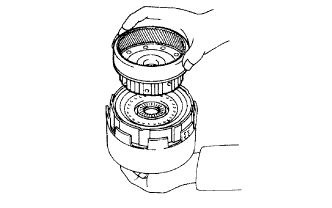
Install the output shaft to the rear planetary gear flange.
-
-
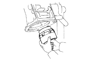
INSTALL SECOND BRAKE PISTON
-
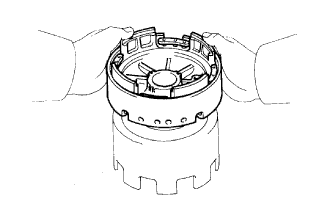
Coat 2 new O-rings with ATF, and install them on the second brake piston.
-
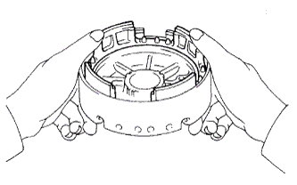
Being careful not to damage the O-rings, and press the second brake piston to the second brake drum with both hands.
-
-
INSTALL SECOND BRAKE PISTON RETURN SPRING SUB-ASSEMBLY
-
Install the piston return spring.
-
Install the second brake piston return spring seat.
-
Place SST on the spring retainer and compress the return spring with a press.
- SST
- 09350-30020 ( 09350-07040 )
CAUTION:
Do not deform the spring sheet. Stop compressing when the spring sheet is lowered to a position 1 to 2 mm (0.0394 to 0.0787 in.) from the snap ring groove.
-
Using a snap ring expander, install the snap ring.
Note
Do not expand the snap ring excessively.
-
-
INSPECT SECOND BRAKE PISTON
-
Check that the second brake piston moves smoothly when applying compressed air to and releasing low-pressure compressed air from the second brake drum.
-
-
INSTALL NO. 4 PLANETARY CARRIER THRUST WASHER
-
Coat the thrust washer with petroleum jelly and install it.
Tech Tips
Make sure that the cutout portions of the thrust washer fit onto the teeth of the spring retainer.
-
-
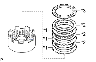
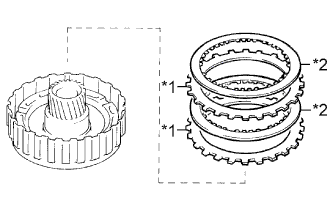
INSTALL FIRST AND REVERSE BRAKE DISC SET
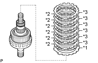
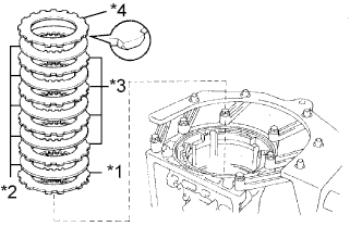
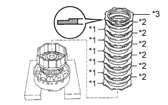
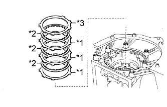
Text in Illustration *1 Flange *2 Disc *3 Plate
-
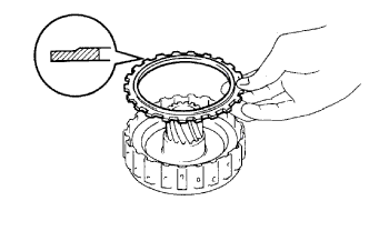
Install the flange with the rounded edge facing upward.
-
Install the 6 discs and 6 plates.
Install in order *1 - *2 - *3 - *2 - *3 - *2 - *3 - *2 - *3 - *2 - *3 - *2 - *3
-
-
INSTALL OUTPUT SHAFT WITH REAR PLANETARY GEAR, NO. 2 1-WAY CLUTCH, FIRST AND REVERSE BRAKE DISC SET AND SECOND BRAKE DRUM
-
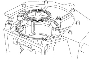
Coat the bearing with petroleum jelly and install it to the case.
Bearing Diameter Item Inside Outside Bearing I 39.38 mm (1.55 in.) 57.94 to 58.36 mm (2.28 to 2.30 in.) Note
Make sure the bearing is installed facing the proper direction.
-
Align the teeth on the flange, discs and plates.
-
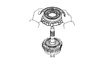
Install the 2nd brake drum to the planetary gear with the snap ring facing upward.
Note
Make sure the oil hole in the drum faces towards the lower side of the transmission case (the side where the valve body is installed).
-
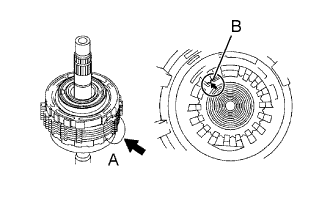
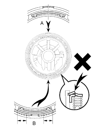
Align the teeth of the planetary gear assembly, indicted by A in the illustration, with the splines of the transmission case, indicated by B in the illustration.
-
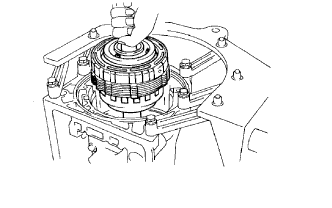
Install the assembled planetary gear.
-
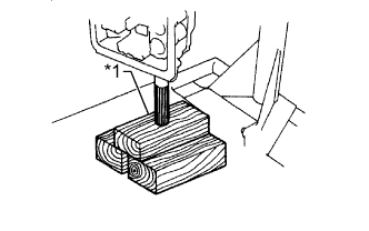
Text in Illustration *1 Wooden Block Place the output shaft on wooden blocks.
-
Using SST, install the snap ring.
- SST
- 09350-30020 ( 09350-07060 )
-
-
SELECT FIRST AND REVERSE BRAKE FLANGE
-
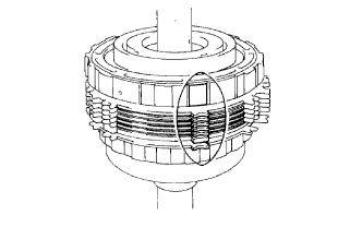
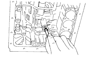
Using a feeler gauge, measure the clearance between the plate and second brake drum.
Standard clearance 0.70 to 1.22 mm (0.0276 to 0.0480 in.) If the clearance is not as specified, select another flange.
If the clearance is not as specified, select a flange of an appropriate thickness from the table below so that the measured value is within the standard range.
Flange Thickness Mark Thickness 55 3.94 to 4.06 mm (0.155 to 0.160 in.) 54 4.14 to 4.26 mm (0.163 to 0.168 in.) 53 4.34 to 4.46 mm (0.171 to 0.176 in.) 52 4.54 to 4.66 mm (0.179 to 0.183 in.) 51 4.74 to 4.86 mm (0.187 to 0.191 in.) 50 4.92 to 5.08 mm (0.194 to 0.200 in.) 66 5.10 to 5.30 mm (0.201 to 0.209 in.) 67 5.30 to 5.50 mm (0.209 to 0.217 in.)
-
-
INSTALL SECOND BRAKE PISTON SLEEVE
-
INSTALL BRAKE DRUM GASKET
-
Coat a new gasket with ATF and install it.
-
-
INSTALL NO. 1 1-WAY CLUTCH ASSEMBLY
-
Install the thrust washer to the second brake piston return spring.
-
Install the 1-way clutch as shown in the illustration.
-
-
INSTALL SECOND BRAKE DISC SET
-
Install the 1.8 mm (0.0709 in.) thick plate with the rounded edge of the plate facing the discs.
-
Install the 5 discs, 4 2.5 mm (0.0984 in.) thick plates and flange.
Install in order *1 - *2 - *3 - *2 - *3 - *2 - *3 - *2 - *3 - *2 - *4 Text in Illustration *1 1.8 mm (0.0709 in.) Thick Plate *2 Disc *3 2.5 mm (0.0984 in.) Thick Plate *4 Flange -
Using a screwdriver, install the snap ring.
-
-
INSPECT SECOND BRAKE
-
Using a feeler gauge, measure the clearance between the snap ring and flange.
Standard clearance 0.62 to 1.98 mm (0.0244 to 0.0780 in.) If the clearance is not as specified, inspect the discs.
-
-
INSTALL SUN GEAR INPUT DRUM SHAFT SNAP RING
-
Using a screwdriver, install the snap ring to the planetary sun gear.
-
-
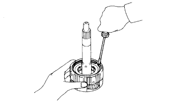
INSTALL SUN GEAR INPUT DRUM
-
Place the planetary sun gear onto a wooden block or similar object.
-
Install the input drum to the planetary sun gear.
-
Using snap ring pliers, install the snap ring.
-
-
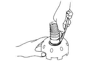
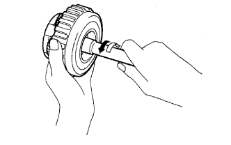
INSTALL SUN GEAR SHAFT OIL SEAL RING
-
Coat the 2 oil seal rings with ATF.
-
Install the 2 oil seal rings to the planetary sun gear.
Tech Tips
After installing the oil seal rings, check that they rotate smoothly.
Note
Do not expand the ring excessively.
-
-
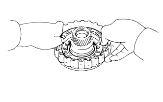
INSTALL NO. 1 1-WAY CLUTCH THRUST WASHER
Tech Tips
Make sure that the tabs of the washer fit into the holes in the sun gear input drum.
-
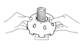
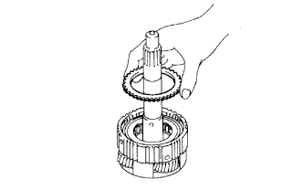
INSTALL PLANETARY SUN GEAR SUB-ASSEMBLY WITH SUN GEAR INPUT DRUM
-
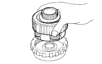
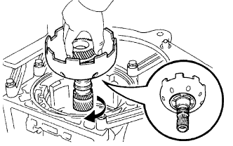
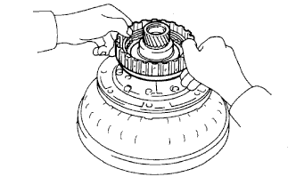
While turning the sun gear clockwise, install it to the 1-way clutch.
Tech Tips
Confirm that the thrust washer is installed correctly.
-
-
INSTALL FRONT PLANETARY GEAR ASSEMBLY
-
Coat the bearing and bearing race with petroleum jelly and install them to the planetary gear.
Bearing and Bearing Race Diameter Item Inside Outside Bearing Race G 33.55 to 33.80 mm (1.32 to 1.33 in.) 47.3 to 47.8 mm (1.86 to 1.88 in.) Bearing G 35.45 to 35.61 mm (1.396 to 1.402 in.) 47.62 to 47.87 mm (1.87 to 1.88 in.) Text in Illustration *1 Bearing Race G *2 Bearing G Note
Make sure the bearing and race are installed facing the proper directions.
-
Install the planetary gear to the sun gear input drum.
-
Using SST, install the snap ring.
- SST
- 09350-30020 ( 09350-07070 )
-
Remove the wooden blocks from under the output shaft.
-
Coat the bearing race with petroleum jelly and install it to the planetary gear.
Bearing Race Diameter Item Inside Outside Bearing Race F 34 to 34.5 mm (1.34 to 1.36 in.) 48.5 to 49 mm (1.91 to 1.93 in.) Note
Be careful to the installation direction of the bearing race.
-
-
INSTALL SECOND COAST BRAKE BAND ASSEMBLY
-
Install the brake band to the case.
-
Install the pin to the brake band as shown in the illustration.
-
Install the E-ring to the pin.
-
-
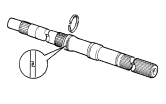
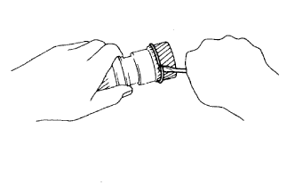
INSTALL INPUT SHAFT OIL SEAL RING
-
Coat the 3 oil seal rings with ATF.
-
Squeeze the ends of the 3 oil seal rings together, and then install them to the forward clutch drum groove.
Note
Do not expand the rings excessively.
Tech Tips
After installing the oil seal rings, check that they rotate smoothly.
-
-
INSTALL FRONT CLUTCH PISTON SUB-ASSEMBLY
-
Coat 2 new O-rings with ATF and install them to the forward clutch piston.
Text in Illustration *1 O-Ring -
Coat a new O-ring with ATF and install it to the forward clutch drum.
-
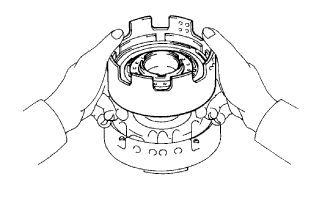
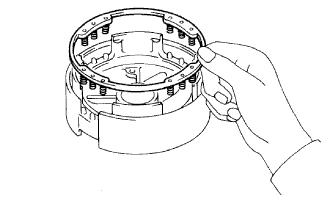
Press the clutch piston into the forward clutch drum with both hands to install it.
Note
Be careful not to damage the O-ring.
-
-
INSTALL FORWARD CLUTCH RETURN SPRING SUB-ASSEMBLY
-
Install the piston return spring.
-
Place SST on the spring retainer, compress the return spring with a press, and then install the snap ring.
- SST
- 09350-30020 ( 09350-07040, 09350-07070 )
Note
Make sure the end gap of the snap ring is not aligned with the spring retainer claw.
-
-
INSTALL FORWARD CLUTCH DISC SET
-
Install the cushion plate.
-
Text in Illustration *1 Plate *2 Disc *3 Flange Install the 6 plates, 6 discs and flange.
Install in order *1 - *2 - *1 - *2 - *1 - *2 - *1 - *2 - *1 - *2 - *1 - *2 - *3 -
Using a screwdriver, install the snap ring.
Note
Make sure the end gap of the snap ring is not aligned with the cutout portion of the forward clutch drum.
-
-
SELECT FORWARD CLUTCH FLANGE
-
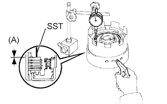
Using SST and a dial indicator, measure the moving distance (A) of the clutch flange at both ends across the diameter while applying and releasing compressed air (392 kPa (4.0 kgf/cm2, 57 psi))
- SST
- 09350-30020 ( 09350-06120 )
Standard moving distance (A) 0.60 to 1.00 mm (0.0236 to 0.0394 in.) If the moving distance (A) is not as specified, select a flange of an appropriate thickness from the table below so that the measured value is within the standard range.
Flange Thickness Mark Thickness 90 2.95 to 3.05 mm (0.116 to 0.120 in.) 91 3.15 to 3.25 mm (0.124 to 0.128 in.) 92 3.35 to 3.45 mm (0.132 to 0.136 in.) 93 3.55 to 3.65 mm (0.140 to 0.144 in.) 94 3.75 to 3.85 mm (0.148 to 0.152 in.) 95 3.95 to 4.05 mm (0.156 to 0.159 in.) 96 4.15 to 4.25 mm (0.163 to 0.167 in.) 97 4.35 to 4.45 mm (0.171 to 0.175 in.)
-
-
INSTALL DIRECT CLUTCH PISTON SUB-ASSEMBLY
-
Coat 2 new O-rings with ATF and install them to the direct clutch piston.
Text in Illustration *1 O-Ring -
Press the clutch piston into the clutch drum with both hands to install it.
Note
Be careful not to damage the O-rings.
-
-
INSTALL DIRECT CLUTCH RETURN SPRING SUB-ASSEMBLY
-
Place SST on the spring retainer and compress the return spring with a press.
- SST
- 09350-30020 ( 09350-07040 )
-
Using SST, install the snap ring.
- SST
- 09350-30020 ( 09350-07070 )
Note
Be sure the end gap of the snap ring is not aligned with the spring retainer claw.
-
-
INSTALL DIRECT CLUTCH DISC SET
-
Install the 3 plates and 3 discs.
-
Install the flange with the flat end facing downward.
Install in order *1 - *2 - *1 - *2 - *1 - *2 - *3 Text in Illustration *1 Plate *2 Disc *3 Flange -
Using a screwdriver, install the snap ring.
Note
Make sure the end gap of the snap ring is not aligned with the cutout portion of the direct clutch drum.
-
-
SELECT DIRECT CLUTCH FLANGE
-
Place the direct clutch to the overdrive support.
-
Using SST and a dial indicator, measure the moving distance (A) of the clutch flange at both ends across the diameter while applying and releasing compressed air (186 to 206 kPa (1.9 to 2.1 kgf/cm2, 27 to 30 psi)).
- SST
- 09350-30020 ( 09350-06120 )
Standard moving distance (A) 0.40 to 0.70 mm (0.0157 to 0.0276 in.) If the moving distance (A) is not as specified, select a flange of an appropriate thickness from the table below so that the measured value is within the standard range.
Flange Thickness Mark Thickness 53 3.25 to 3.35 mm (0.128 to 0.132 in.) 54 3.35 to 3.45 mm (0.132 to 0.136 in.) 55 3.45 to 3.55 mm (0.136 to 0.140 in.) 56 3.55 to 3.65 mm (0.140 to 0.144 in.) 57 3.65 to 3.75 mm (0.144 to 0.148 in.) 58 3.75 to 3.85 mm (0.148 to 0.152 in.)
-
-
INSTALL DIRECT CLUTCH ASSEMBLY
-
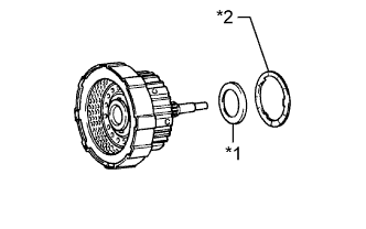
Install the bearing and thrust washer to the forward clutch.
Bearing Diameter Item Inside Outside Bearing D 33.55 to 33.80 mm (1.32 to 1.33 in.) 47.62 to 47.87 mm (1.87 to 1.88 in.) Text in Illustration *1 Bearing D *2 Thrust Washer -
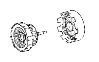
Install the direct clutch to the forward clutch.
-
-
INSTALL FRONT PLANETARY RING GEAR SUB-ASSEMBLY
-
Coat the bearing race and bearing with petroleum jelly and install them to the forward clutch.
Bearing Diameter Item Inside Outside Bearing Race E 25.98 mm (1.02 in.) 48.87 mm (1.92 in.) Bearing E 25.94 to 26.07 mm (1.02 to 1.03 in.) 46.62 to 46.87 mm (1.84 to 1.85 in.) Text in Illustration *1 Bearing Race E *2 Bearing E Note
Make sure the bearing and race are installed facing the proper directions.
-
Coat the bearing race with petroleum jelly and install it to the front planetary ring gear.
Bearing Race Diameter Item Inside Outside Bearing Race E 26.5 to 27.0 mm (1.04 to 1.06 in.) 47.02 mm (1.85 in.) Note
Make sure the bearing race is installed facing the proper directions.
-
Align the teeth of the discs in the forward clutch.
-
Align the splines of the planetary ring gear with the teeth of the discs and install the planetary ring gear to the forward clutch.
-
-
INSTALL DIRECT CLUTCH ASSEMBLY WITH FORWARD CLUTCH ASSEMBLY
-
Coat the bearing with petroleum jelly and install it to the ring gear.
Bearing Diameter Item Inside Outside Bearing F 35 to 35.3 mm (1.38 to 1.39 in.) 50.50 to 53.75 mm (2.11 to 2.12 in.) Text in Illustration *1 Bearing F Note
Make sure the bearing is installed facing the proper directions.
-
Install the assembled direct clutch, forward clutch and front planetary ring gear to the transmission case.
-
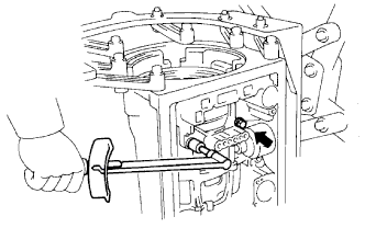
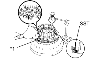
Using a vernier caliper, measure the distance between the sun gear input drum and direct clutch drum as shown in the illustration.
Standard distance 5.3 to 7.3 mm (0.209 to 0.287 in.) If the distance is not as specified, check for improper installation.
-
Coat the bearing with petroleum jelly and install it to the forward clutch.
Bearing Diameter Item Inside Outside Bearing D 33.55 to 33.80 mm (1.32 to 1.33 in.) 47.62 to 47.87 mm (1.87 to 1.88 in.) Note
Make sure the bearing is installed facing the proper directions.
-
-
INSTALL SECOND COAST BRAKE PISTON ROD
-
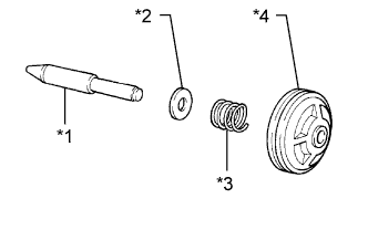
*1 Piston Rod *2 Washer Plate *3 Compression Spring *4 Piston Install the washer plate, compression spring and piston to the piston rod.
-
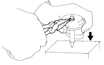
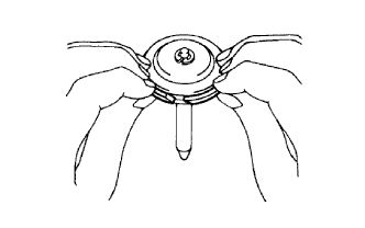
Firmly press the piston down to compress the compression spring.
-
Install the E-ring.
-
-
INSTALL SECOND COAST BRAKE PISTON OIL SEAL RING
-
Coat a new oil seal ring with ATF.
-
Spread the ends of the ring to install the oil seal ring to the piston groove. Then squeeze its ends together.
Note
Do not spread the ring ends excessively.
-
-
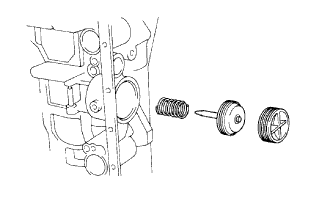
INSTALL SECOND COAST BRAKE PISTON ASSEMBLY
-
Coat 2 new O-rings with ATF and install them to the second coast brake cover.
-
Install the spring, piston assembly and cover to the case.
-
Using SST, install the snap ring.
- SST
- 09350-30020 ( 09350-07060 )
-
-
INSPECT PISTON STROKE OF SECOND COAST BRAKE
-
Using a waterproof pen, place a mark on the second coast brake piston rod as shown in the illustration.
Text in Illustration *1 Piston Rod *2 Mark -
Using SST, measure the piston stroke while applying and releasing a compressed air (392 kPa (4.0 kgf/cm2, 57 psi)).
- SST
- 09240-00020
Standard piston stroke 1.5 to 3.0 mm (0.0591 to 0.118 in.) If the piston stroke is not as specified, inspect the brake band.
If the piston stroke is not as specified, select a piston rod of an appropriate length from the table below so that the measured value is within the standard range.
Piston Rod Length Groove Mark Length Without 78.3 to 78.5 mm (3.08 to 3.09 in.) With 79.8 to 80.0 mm (3.14 to 3.15 in.)
-
-
INSTALL OVERDRIVE CLUTCH DRUM OIL SEAL RING
-
Coat 2 new oil seal rings with ATF.
-
Squeeze the ends of the 2 oil seal rings together, and then install them to the stator shaft groove.
Note
Do not expand the rings excessively.
Tech Tips
After installing the oil seal rings, check that they rotate smoothly.
-
Coat the thrust washer with petroleum jelly and install it to the overdrive support.
Tech Tips
Make sure that the tab of the washer fits into the groove of the overdrive support.
-
-
INSTALL OVERDRIVE BRAKE PISTON
-
Coat 2 new O-rings with ATF and install them to the overdrive brake piston.
Text in Illustration *1 O-Ring -
Press the brake piston into the overdrive support with both hands to install it.
Note
Be careful not to damage the O-rings.
-
-
INSTALL OVERDRIVE BRAKE RETURN SPRING SUB-ASSEMBLY
-
Install the return spring to the brake piston.
-
Place SST on the spring retainer and compress the return spring with a press.
- SST
- 09350-30020 ( 09350-07030 )
-
Using a screwdriver, install the snap ring.
Note
Make sure the end gap of the snap ring is not aligned with the cutout portion of the overdrive support.
Tech Tips
-
After assembling the overdrive support assembly completely, align the position of the piston with A in the illustration.
-
Align the end gap of the snap ring with B in the illustration.
-
Make sure that the snap ring is not on the part of return spring that prevents the spring from coming off. Check this for the 8 places.
-
-
-
INSPECT PISTON OPERATION OF OVERDRIVE BRAKE
-
Place the overdrive support assembly to the direct clutch assembly.
-
Apply compressed air (392 kPa (4 kgf/cm2, 57 psi)) into the oil passage and check that the overdrive brake piston moves smoothly.
-
-
INSTALL OVERDRIVE BRAKE ASSEMBLY
-
Coat the bearing and bearing race with petroleum jelly and install them to the overdrive brake assembly.
Bearing and Bearing Race Diameter Item Inside Outside Bearing C 33.75 to 33.85 mm (1.329 to 1.333 in.) 49.8 to 50.3 mm (1.96 to 1.98 in.) Bearing Race D 36.5 to 37 mm (1.44 to 1.46 in.) 50.75 to 50.95 mm (2.00 to 2.01 in.) Text in Illustration *1 Bearing C *2 Bearing Race D Note
Make sure the bearing and race are installed facing the proper directions.
-
Confirm that the thrust washer is installed correctly.
Tech Tips
Make sure that the tab of the washer fits into the hole on the overdrive brake assembly.
-
Using the 2 bolts of SST, aim the bolt and oil holes of the overdrive brake assembly toward the valve body side, and align them with the bolt holes of the transmission case. Then install the overdrive brake assembly.
- SST
- 09350-30020 ( 09350-07020 )
-
Temporarily install the 2 bolts.
-
Using SST, install the snap ring.
- SST
- 09350-30020 ( 09350-07060 )
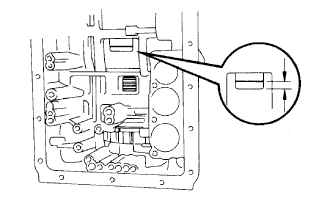
Standard distance A 24 mm (0.945 in.) Tech Tips
Install the snap ring with the open end facing toward the valve body.
-
Tighten the 2 bolts.
- Torque:
- 25 N*m { 260 kgf*cm, 19 ft.*lbf }
-
-
INSPECT OUTPUT SHAFT END PLAY
-
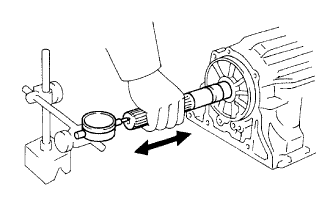
Using a dial indicator, measure the end play of the output shaft while moving it by hand.
Standard end play 0.30 to 1.04 mm (0.0118 to 0.0409 in.) If the end play is not as specified, check for improper installation.
-
Check that the output shaft rotates smoothly.
-
-
INSTALL OVERDRIVE BRAKE DISC SET
-
Install the 3 plates, 3 discs and flange.
Install in order *1 - *2 - *1 - *2 - *1 - *2 - *3 Text in Illustration *1 Plate *2 Disc *2 Flange -
Using a screwdriver, install the snap ring.
-
-
SELECT OVERDRIVE BRAKE FLANGE
-
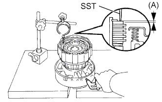
Place SST and a dial indicator on the overdrive brake piston.
- SST
- 09350-30020 ( 09350-06120 )
-
Measure the stroke while applying and releasing compressed air (392 kPa (4.0 kgf/cm2, 57 psi))
Standard piston stroke 1.75 to 2.05 mm (0.0689 to 0.0807 in.) If the piston stroke is not as specified, parts may have been assembled incorrectly. Check and reassemble again.
If the piston stroke is still outside the standard, select a flange of an appropriate thickness from the table below so that the measured value is within the standard range.
Flange Thickness Mark Thickness 33 3.25 to 3.35 mm (0.128 to 0.132 in.) 35 3.45 to 3.55 mm (0.136 to 0.140 in.) 36 3.55 to 3.65 mm (0.140 to 0.144 in.) 37 3.65 to 3.75 mm (0.144 to 0.148 in.) 38 3.75 to 3.85 mm (0.148 to 0.152 in.) 39 3.85 to 3.95 mm (0.152 to 0.156 in.) 40 3.95 to 4.05 mm (0.156 to 0.159 in.)
-
-
INSTALL OVERDRIVE PLANETARY RING GEAR FLANGE
-
Install the ring gear flange to the overdrive planetary ring gear.
-
Using a screwdriver, install the snap ring.
-
-
INSTALL OVERDRIVE PLANETARY RING GEAR
-
Coat the bearing race with petroleum jelly and install it to the overdrive planetary ring gear flange.
Bearing Race Diameter Item Inside Outside Bearing Race C 37.1 to 37.3 mm (1.46 to 1.47 in.) 58.70 to 58.95 mm (2.31 to 2.32 in.) Text in Illustration *1 Bearing Race C Note
Make sure the bearing race is installed facing the proper directions.
-
Install the ring gear.
-
-
INSTALL NO. 3 OVERDRIVE PLANETARY GEAR THRUST WASHER
-
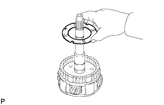
Install the thrust washer to the overdrive planetary gear with the grooves facing upward.
-
-
INSTALL OVERDRIVE 1-WAY CLUTCH
-
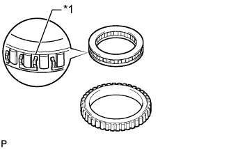
Install the 2 retainers to the 1-way clutch.
-
Install the 1-way clutch to the outer race with the flange of the 1-way clutch facing upward.
Text in Illustration *1 Flange -
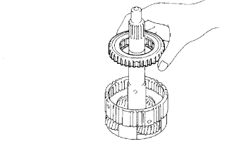
Install the overdrive 1-way clutch and outer race to the overdrive planetary gear.
-
-
INSTALL OVERDRIVE RETAINING PLATE
-
Install the retaining plate.
-
Using a screwdriver, install the snap ring.
-
-
INSPECT OVERDRIVE 1-WAY CLUTCH
-
Hold the overdrive direct clutch drum and turn the input shaft. Check that the input shaft can be turned clockwise freely and locks when turned counterclockwise.
Text in Illustration Lock Free
-
-
INSTALL OVERDRIVE DIRECT CLUTCH PISTON SUB-ASSEMBLY
-
Coat 2 new O-rings with ATF, and install them to the overdrive direct clutch piston.
-
Press the clutch piston into the clutch drum with both hands to install it.
Note
Be careful not to damage the O-rings.
-
-
INSTALL OVERDRIVE BRAKE RETURN SPRING SUB-ASSEMBLY
-
Install the overdrive brake return spring on the overdrive direct clutch piston.
-
Place SST on the spring retainer and compress the return spring with a press.
- SST
- 09350-30020 ( 09350-07040 )
-
Using a screwdriver, install the snap ring.
Text in Illustration *1 Retainer Claw Note
-
Do not deform the spring sheet. Stop compressing when the spring sheet is lowered to a position 1 to 2 mm (0.0394 to 0.0787 in.) from the snap ring groove.
-
Make sure the end gap of the snap ring is not aligned with the spring retainer claw.
-
-
-
INSTALL OVERDRIVE DIRECT CLUTCH DISC SET
-
Install the 2 plates and 2 discs.
Install in order *1 - *2 - *1 - *2 Text in Illustration *1 Plate *2 Disc -
Install the flange with the flat end facing downward.
-
Using a screwdriver, install the snap ring.
-
-
SELECT OVERDRIVE CLUTCH FLANGE
-
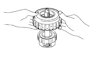
Place the oil pump onto the torque converter clutch, and then place the overdrive direct clutch drum assembly to the oil pump.
-
Text in Illustration *1 Vinyl Tape Using SST and a dial indicator, measure the overdrive direct clutch piston stroke while applying and releasing compressed air (392 kPa (4.0 kgf/cm2, 57 psi)).
- SST
- 09350-30020 ( 09350-06120 )
Standard piston stroke 1.85 to 2.15 mm (0.0728 to 0.0846 in.) If the piston stroke is not as specified, parts may have been assembled incorrectly. Check and reassemble again.
If the piston stroke is still not as specified, select another flange.
If the piston stroke is still outside the standard, select a flange of an appropriate thickness from the table below so that the measured value is within the standard range.
Flange Thickness Mark Thickness 21 3.05 to 3.15 mm (0.120 to 0.124 in.) 20 3.15 to 3.25 mm (0.124 to 0.128 in.) 19 3.25 to 3.35 mm (0.128 to 0.132 in.) 18 3.35 to 3.45 mm (0.132 to 0.136 in.) 17 3.45 to 3.55 mm (0.136 to 0.140 in.) 16 3.55 to 3.65 mm (0.140 to 0.144 in.)
-
-
INSTALL OVERDRIVE DIRECT CLUTCH DRUM
-
Align the teeth of the discs in the direct clutch assembly.
-
Install the direct clutch drum assembly to the overdrive planetary gear.
-
-
INSTALL OVERDRIVE PLANETARY GEAR ASSEMBLY WITH DIRECT CLUTCH ASSEMBLY AND OVERDRIVE 1-WAY CLUTCH ASSEMBLY
-
Text in Illustration *1 Bearing B Coat the bearing with petroleum jelly and install it to the ring gear.
Bearing Diameter Item Inside Outside Bearing B 31.45 to 31.70 mm (1.24 to 1.25 in.) 49.1 to 49.4 mm (1.93 to 1.94 in.) Note
Make sure the bearing is installed facing the proper directions.
-
Text in Illustration *1 Bearing Race B Coat the bearing race with petroleum jelly and install it to the planetary gear.
Bearing Race Diameter Item Inside Outside Bearing Race B 33.0 to 33.25 mm (1.30 to 1.31 in.) 49.9 to 50.4 mm (1.96 to 1.98 in.) Note
Make sure the bearing race is installed facing the proper directions.
-
Install the overdrive planetary gear with overdrive direct clutch and 1-way clutch.
-
Place SST on the transmission case.
- SST
- 09350-36010 ( 09350-06090 )
-
Using a vernier caliper, measure the distance between the top of SST and clutch drum.
Standard distance 15.5 to 16.5 mm (0.610 to 0.650 in.) If the distance is not as specified, check for improper installation.
-
Text in Illustration *1 Bearing A Coat the bearing with petroleum jelly and install it to the overdrive direct clutch.
Bearing Diameter Item Inside Outside Bearing A 29.0 to 29.25 mm (1.14 to 1.15 in.) 50.04 to 50.34 mm (1.97 to 1.98 in.) Note
Make sure the bearing is installed facing the proper directions.
-
-
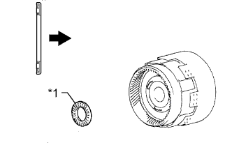
INSTALL OIL PUMP ASSEMBLY
-
Coat the bearing race with petroleum jelly and install it to the oil pump.
Bearing Race Diameter Item Inside Outside Bearing Race A 28.45 mm (1.12 in.) 29.9 to 30.1 mm (1.18 to 1.19 in.) Text in Illustration *1 Bearing Race A Note
Make sure the bearing race is installed facing the proper directions.
-
Coat a new O-ring with ATF, and install it to the pump body.
-
Slide the oil pump onto the input shaft, align the bolt holes of the oil pump assembly with the bolt holes of the transmission case and install the oil pump.
-
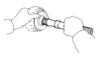
Hold the input shaft, and lightly press the oil pump body to slide the oil seal rings to the overdrive direct clutch drum.
Note
Do not forcefully push on the oil pump as the oil seal rings will stick to the direct clutch drum.
-
Install the 7 bolts.
- Torque:
- 21 N*m { 215 kgf*cm, 16 ft.*lbf }
-
-
INSPECT INPUT SHAFT ROTATION
-
Make sure the input shaft rotates smoothly.
-
-
INSPECT INDIVIDUAL PISTON OPERATION
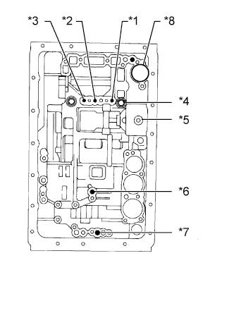
Text in Illustration *1 Overdrive Direct Clutch (C1) *2 Direct Clutch (C2) *3 Forward Clutch (C3) *4 Overdrive Brake (B1) *5 Second Coast Brake (B2) *6 Second Brake (B3) *7 First and Reverse Brake (B4) *8 C-0 Accumulator Piston Hole
-
Check the operating sound while applying compressed air to the oil hole indicated in the illustration.
Tech Tips
When inspecting the overdrive direct clutch, check the operation sound with the C-0 accumulator piston hole closed.
If there is no sound, disassemble and check the parts installation condition.
-
-
INSTALL MANUAL VALVE LEVER SHAFT OIL SEAL
-
Using SST and a hammer, tap in 2 new oil seals.
- SST
- 09350-30020 ( 09350-07110 )
-
Coat the lips of the oil seals with MP grease.
-
-
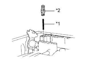
INSTALL MANUAL VALVE LEVER SHAFT
-
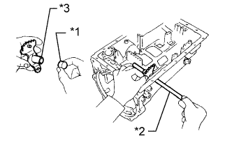
Install a new spacer to the manual valve lever.
Text in Illustration *1 Spacer *2 Manual Valve Lever Shaft *3 Manual Valve Lever -
Pass the manual valve lever shaft through the transmission case and the manual valve lever to install it.
-
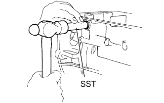
Using a hammer, tap in a new spring pin.
-
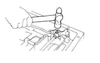
Align the manual valve lever indentation with the spacer hole, and stake them with the punch.
-
Check that the shaft rotates smoothly.
-
-
INSTALL PARKING LOCK PAWL
Text in Illustration *1 E-Ring *2 Parking Lock Pawl Shaft *3 Parking Lock Pawl *4 Spring
-
Install the E-ring to the parking lock pawl shaft.
-
Install the parking lock pawl, shaft and spring.
-
-
INSTALL PARKING LOCK ROD SUB-ASSEMBLY
-
Connect the parking lock rod to the manual valve lever to install it.
-
-
INSTALL PARKING LOCK PAWL BRACKET
-
Install the parking lock pawl bracket to the transmission case and with the 3 bolts.
- Torque:
- 7.4 N*m { 75 kgf*cm, 65 in.*lbf }
-
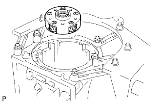
Text in Illustration *1 Manual Valve Lever *2 Planetary Ring Gear *3 Parking Lock Pawl Shift the manual valve lever to the P position, and confirm that the planetary ring gear is correctly locked by the parking lock pawl.
-
-
INSTALL C-0 ACCUMULATOR PISTON
-
Coat a new O-ring with ATF and install it to the piston.
-
Install the 2 springs and accumulator piston to the hole.
Accumulator Spring Diameter Item Free Length
Outer Diameter
Color C-0 Inner Spring 46.0 mm (1.81 in.)
14.02 mm (0.552 in.)
Yellow C-0 Outer Spring 74.6 mm (2.94 in.)
20.9 mm (0.823 in.)
Orange
-
-
INSTALL B-0 ACCUMULATOR PISTON
-
Coat 2 new O-rings with ATF and install them to the piston.
-
Install the spring and accumulator piston to the hole.
Accumulator Spring Diameter Item Free Length
Outer Diameter
Color B-0 Spring 63.6 mm (2.50 in.)
16.0 mm (0.630 in.)
Red
-
-
INSTALL C-2 ACCUMULATOR PISTON
-
Coat 2 new O-rings with ATF and install them to the piston.
-
Install the 2 springs and accumulator piston to the hole.
Accumulator Spring Diameter Item Free Length
Outer Diameter
Color C-2 Inner Spring 42.06 mm (1.66 in.)
14.7 mm (0.579 in.)
Pink C-2 Outer Spring 68.53 mm (2.70 in.)
20.2 mm (0.795 in.)
Blue
-
-
INSTALL B-2 ACCUMULATOR PISTON
-
Coat 2 new O-rings with ATF and install them to the piston.
-
Install the spring and accumulator piston to the hole.
Accumulator Spring Diameter Item Free Length
Outer Diameter
Color B-2 Spring 70.50 mm (2.78 in.)
19.9 mm (0.783 in.)
Light Green
-
-
INSTALL CHECK BALL BODY
Text in Illustration *1 Spring *2 Check Ball Body
-
Install the spring and check ball body.
-
-
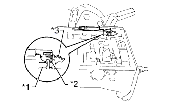
INSTALL TRANSMISSION VALVE BODY ASSEMBLY
-
Install the valve body and align the groove of the manual valve with the pin of the manual valve lever.
Text in Illustration *1 Manual Valve *2 Pin *3 Manual Valve Lever -
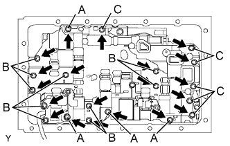
Install the 20 bolts.
- Torque:
- 11 N*m { 110 kgf*cm, 8 ft.*lbf }
Tech Tips
Each bolt length is indicated below.
23 mm (0.906 in.) for A
28 mm (1.10 in.) for B
36 mm (1.42 in.) for C
-
-
INSTALL TRANSMISSION WIRE
-
Coat a new O-ring with ATF and install it to the transmission wire.
-
Install the transmission wire to the case, and then install the stopper plate with the bolt.
- Torque:
- 5.4 N*m { 55 kgf*cm, 48 in.*lbf }
-
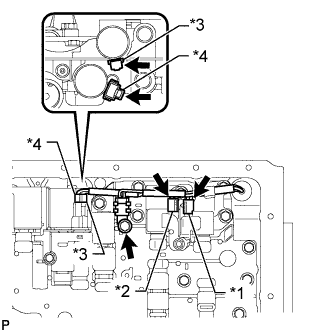
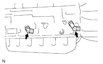
Text in Illustration *1 White *2 Black *3 Orange/Green *4 Yellow/Brown Connect the 4 connectors to the 4 shift solenoid valves.
-
Connect the temperature sensor with temperature sensor clamp and the bolt.
- Torque:
- 9.8 N*m { 100 kgf*cm, 87 ft.*lbf }
-
-
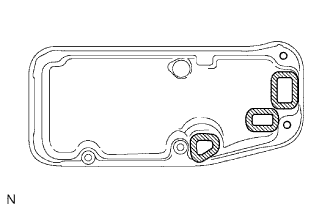
INSTALL VALVE BODY OIL STRAINER ASSEMBLY
-
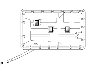
Install 3 new gaskets to the oil strainer.
-
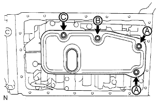
Install the oil strainer with the 4 bolts.
- Torque:
- 11 N*m { 110 kgf*cm, 8 ft.*lbf }
Tech Tips
Each bolt length is indicated below.
14 mm (0.55 in.) for A
20 mm (0.79 in.) for B
23 mm (0.91 in.) for C
-
-
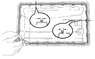
INSTALL OIL CLEANER MAGNET
-
Install the 3 magnets.
-
-
INSTALL AUTOMATIC TRANSMISSION OIL PAN SUB-ASSEMBLY
-
Remove all old seal packing from the contact surfaces of the transmission case and oil pan.
Note
Be careful not to drop oil on the contact surfaces of the transmission case and oil pan.
-
Apply seal packing to the oil pan.
Seal packing Toyota Genuine Seal Packing 1281, Three Bond 1281 or equivalent Seal diameter 2 to 3 mm (0.0787 to 0.118 in.) -
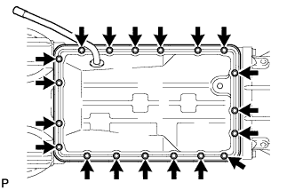
Install the oil pan with the 19 bolts.
- Torque:
- 7.4 N*m { 75 kgf*cm, 65 in.*lbf }
-
-
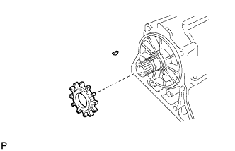
INSTALL SENSOR ROTOR
-
Install the key on the output shaft.
-
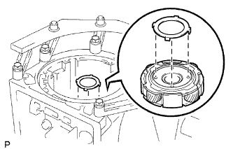
Align the groove of the sensor rotor with the key and install the sensor rotor.
-
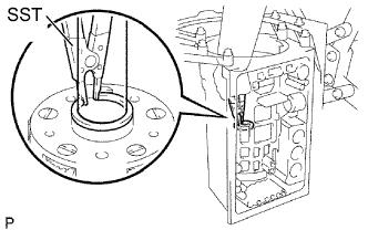
Using snap ring pliers, install the snap ring.
-
-
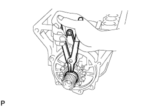
INSTALL TRANSFER CASE REAR ADAPTER OIL RECEIVER
-
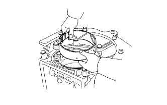
Install the transfer case rear adaptor oil receiver to the rear transfer adaptor.
-
Using snap ring expander, install the snap ring.
-
-
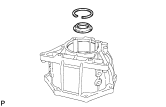
INSTALL TRANSFER CASE ADAPTER REAR OIL SEAL
-
Coat the lip of a new oil seal with ATF.
-
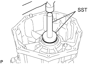
Using SST and a hammer, tap in the oil seal.
- SST
- 09950-60010 ( 09951-00560 )
- 09950-70010 ( 09951-07150 )
Standard depth 0 to 1 mm (0 to 0.394 in.)
-
-
INSTALL REAR TRANSFER ADAPTER
-
Clean the threads of the bolts and case with non-residue solvent.
-
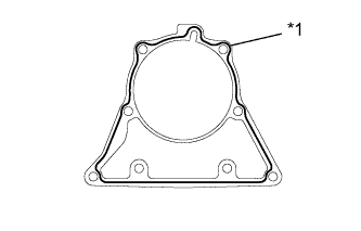
Text in Illustration *1 Seal Packing Apply seal packing to the rear adaptor transfer.
Seal packing Toyota Genuine Seal Packing 1281, Three Bond 1281 or equivalent Seal diameter 1.0 to 1.5 mm (0.0394 to 0.0591 in.) -
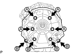
Install the rear adaptor transfer with the 8 bolts.
- Torque:
- 34 N*m { 345 kgf*cm, 25 ft.*lbf }
Tech Tips
Each bolt length is indicated below.
50 mm (1.97 in.) for A
40 mm (1.58 in.) for B
-
-
INSTALL AUTOMATIC TRANSMISSION HOUSING
-
Clean the threads of the bolts and case with non-residue solvent.
-
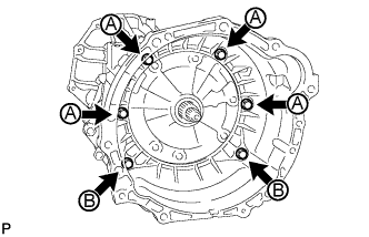
Apply adhesive to the 6 bolts.
Adhesive Toyota Genuine Adhesive 1324, Three Bond 1324 or equivalent -
Install the transmission housing with the 6 bolts.
- Torque:
- for 14 mm bolt A
- 34 N*m { 345 kgf*cm, 25 ft.*lbf }
- for 17 mm bolt B
- 57 N*m { 585 kgf*cm, 42 ft.*lbf }
-
-
INSTALL SPEED SENSOR SP2
-
Install a new O-ring to the sensor.
-
Install the sensor with the bolt.
- Torque:
- 5.4 N*m { 55 kgf*cm, 48 in.*lbf }
-
-
INSTALL SPEED SENSOR NC0
-
Install a new O-ring to the sensor.
-
Install the speed sensor with the bolt.
- Torque:
- 5.4 N*m { 55 kgf*cm, 48 in.*lbf }
-
-
INSTALL OIL COOLER TUBE UNION
-
Coat 2 new O-rings with ATF and install one to each tube union.
- Torque:
- 29 N*m { 300 kgf*cm, 22 ft.*lbf }
-
-
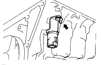
INSTALL AUTOMATIC TRANSMISSION FLUID TEMPERATURE SENSOR
-
Coat a new O-ring with ATF and install it to the sensor.
-
Install the sensor.
- Torque:
- 29 N*m { 300 kgf*cm, 22 ft.*lbf }
-
-
INSTALL PARK/NEUTRAL POSITION SWITCH ASSEMBLY
-
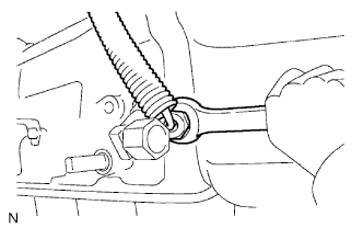
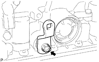
Install the park/neutral position switch to the manual valve lever shaft, and temporarily install the adjusting bolt.
-
Install a new lock washer and the nut.
- Torque:
- 7.0 N*m { 71 kgf*cm, 62 in.*lbf }
-
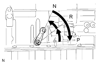
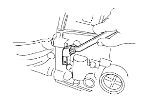
Turn the control shaft lever LH clockwise until it stops, and then turn it counterclockwise 2 notches to set it to the N position.
-
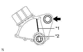
Text in Illustration *1 Neutral Basic Line *2 Groove Align the neutral basic line with the switch groove, as shown in the illustration, and tighten the adjusting bolt.
- Torque:
- 13 N*m { 130 kgf*cm, 9 ft.*lbf }
-
Using a screwdriver, bend the tabs of the lock washer.
-
-
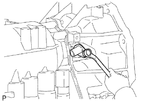
INSTALL TRANSMISSION CONTROL SHAFT LEVER LH
-
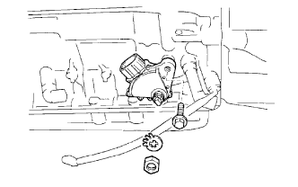
Install the control shaft lever with the washer and nut.
- Torque:
- 16 N*m { 160 kgf*cm, 12 ft.*lbf }
-
-
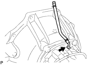
INSTALL BREATHER HOSE
-
INSTALL DRAIN PLUG
-
Install a new gasket and the drain plug.
- Torque:
- 20 N*m { 204 kgf*cm, 15 ft.*lbf }
-