AUTOMATIC TRANSMISSION UNIT DISASSEMBLY

-
REMOVE DRAIN PLUG SUB-ASSEMBLY
-
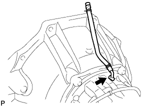
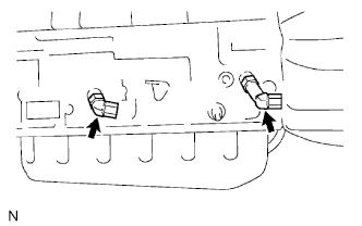
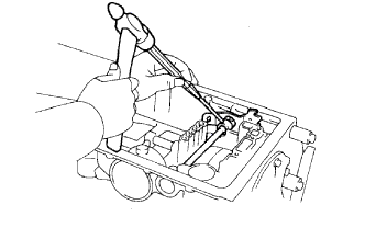
REMOVE BREATHER HOSE
-
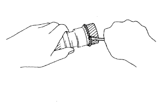
Remove the breather hose plug with the breather hose.
-
Remove the breather hose from the breather hose plug.
-
-
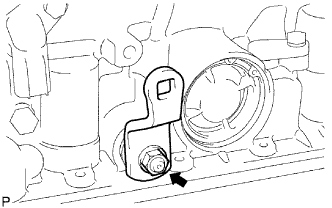
REMOVE TRANSMISSION CONTROL SHAFT LEVER LH
-
Remove the nut, spring washer and control shaft lever.
-
-
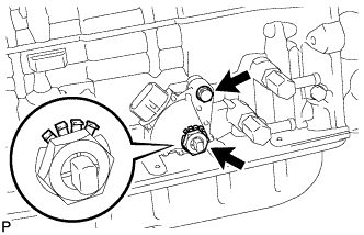
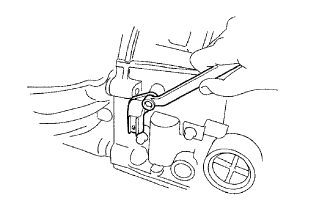
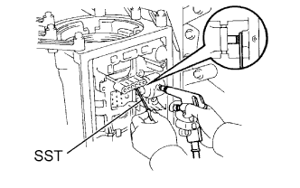
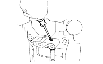
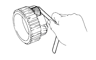
REMOVE PARK/NEUTRAL POSITION SWITCH ASSEMBLY
-
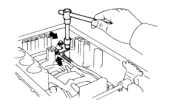
Using a screwdriver, bend the tab of the lock washer.
-
Remove the nut and lock washer.
-
Remove the bolt and park/neutral position switch.
-
-
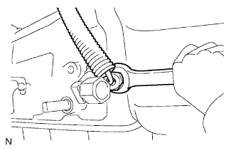
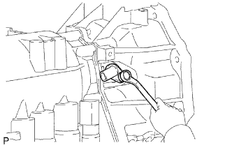
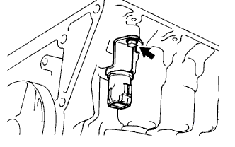
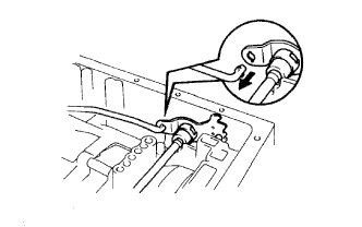
REMOVE ATF TEMPERATURE SENSOR
-
Remove the sensor.
-
Remove the O-ring from the sensor.
-
-
REMOVE OIL COOLER TUBE UNION
-
Remove the 2 tube unions.
-
Remove the O-ring from each tube union.
-
-
REMOVE SPEED SENSOR NC0
-
Remove the bolt and sensor.
-
Remove the O-ring from the sensor.
-
-
REMOVE SPEED SENSOR SP2
-
Remove the bolt and sensor.
-
Remove the O-ring from the sensor.
-
-
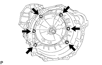
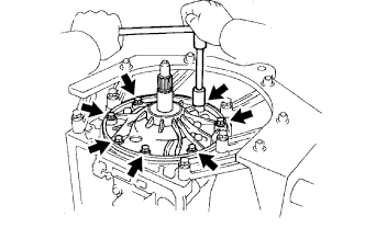
REMOVE AUTOMATIC TRANSMISSION HOUSING
-
Remove the 6 bolts.
-
Remove the transmission housing.
-
-
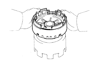
FIX TRANSMISSION CASE
-
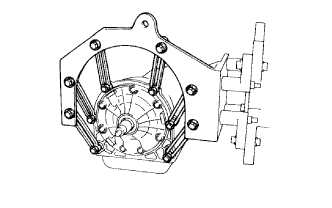
Install the transmission case to an overhaul attachment.
-
-
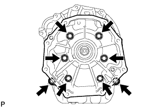
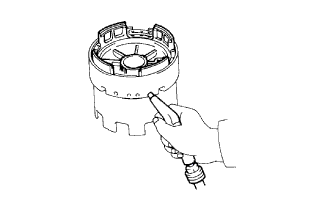
REMOVE REAR TRANSFER ADAPTER
-
Remove the 8 bolts.
-
Remove the rear transfer adaptor.
-
-
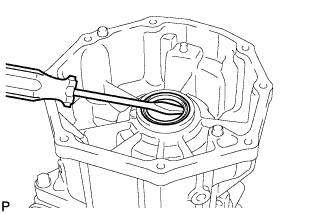
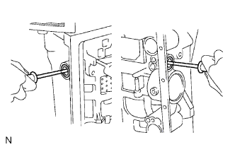
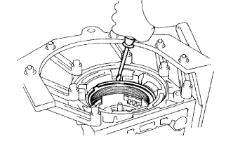
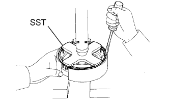
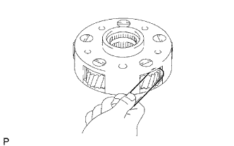
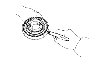
REMOVE TRANSFER CASE ADAPTER REAR OIL SEAL
-
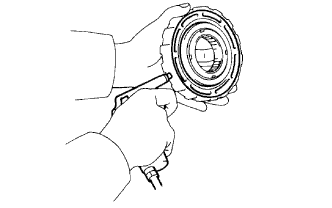
Using a screwdriver, pry out the oil seal.
-
-
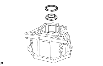
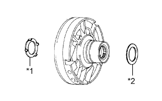
REMOVE TRANSFER CASE REAR ADAPTER OIL RECEIVER
-
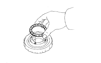
Using snap ring expander, remove the snap ring.
-
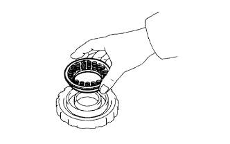
Remove the transfer case rear adaptor oil receiver from the rear transfer adaptor.
-
-
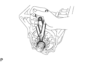
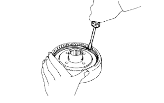
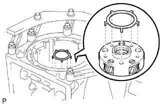
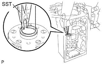
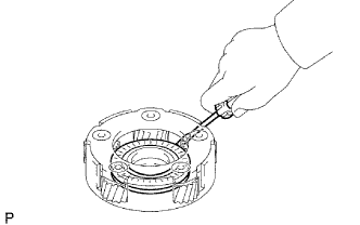
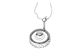
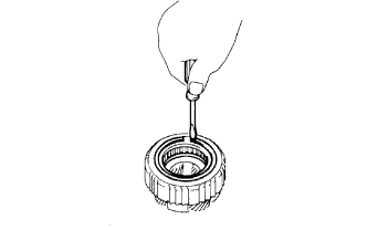
REMOVE SENSOR ROTOR
-
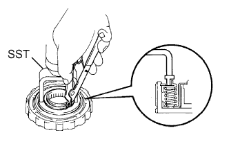
Using snap ring expander, remove the snap ring.
-
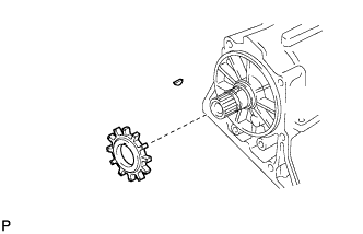
Remove the sensor rotor and key.
-
-
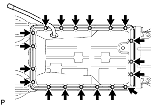
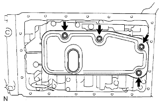
REMOVE AUTOMATIC TRANSMISSION OIL PAN SUB-ASSEMBLY
Note
Do not turn the transmission over as this will contaminate the valve body with foreign matter located at the bottom of the pan.
-
Remove the 19 bolts.
-
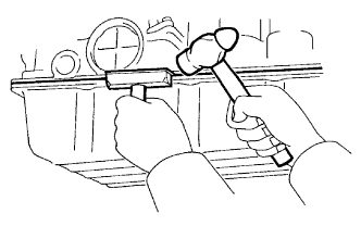
Insert the blade of an oil pan seal cutter between the transmission case and oil pan, and cut off the applied sealer.
Note
Be careful not to damage the oil pan and flange.
-
Remove the pan from the transmission case.
-
-
INSPECT AUTOMATIC TRANSMISSION OIL PAN SUB-ASSEMBLY
-
Remove the magnets and use them to collect steel particles.
-
Carefully look at the foreign matter and particles in the pan and on the magnets to anticipate the type of wear you will find in the transmission.
-
Steel (magnetic): bearing, gear and clutch plate wear.
-
Brass (non-magnetic): bush wear.
-
-
-
REMOVE VALVE BODY OIL STRAINER ASSEMBLY
-
Turn over the transmission.
-
Remove the 4 bolts and the valve body oil strainer from the valve body.
-
Remove the 3 gaskets from the oil strainer.
-
-
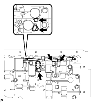
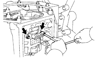
REMOVE TRANSMISSION WIRE
-
Remove the bolt and temperature sensor clamp, and disconnect the temperature sensor.
-
Disconnect the 4 connectors from the shift solenoid valves.
-
Remove the bolt and stopper plate from the case.
-
Pull out the transmission wire from the transmission case to remove it.
-
Remove the O-ring from the transmission wire connector.
-
-
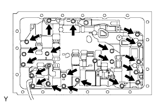
REMOVE TRANSMISSION VALVE BODY ASSEMBLY
-
Remove the 20 bolts and valve body.
-
-
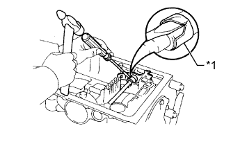
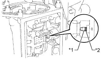
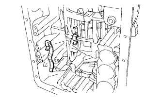
REMOVE CHECK BALL BODY
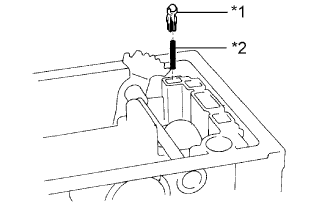
Text in Illustration *1 Check Ball Body *2 Spring
-
Remove the check ball body and spring.
-
-
REMOVE B-2 ACCUMULATOR PISTON

-
Apply compressed air to the oil hole to remove the B-2 accumulator piston and spring.
-
Remove the 2 O-rings from the piston.
-
-
REMOVE C-2 ACCUMULATOR PISTON
-
Apply compressed air to the oil hole to remove the C-2 accumulator piston and 2 springs.
-
Remove the 2 O-rings from the piston.
-
-
REMOVE B-0 ACCUMULATOR PISTON
-
Apply compressed air to the oil hole to remove the B-0 accumulator piston and spring.
-
Remove the 2 O-rings from the piston.
-
-
REMOVE C-0 ACCUMULATOR PISTON
-
Apply compressed air to the oil hole to remove the C-0 accumulator piston and 2 springs.
-
Remove the O-ring from the piston.
-
-
REMOVE PARKING LOCK PAWL BRACKET
-
Remove the 3 bolts and bracket.
-
-
REMOVE PARKING LOCK ROD SUB-ASSEMBLY
-
Disconnect the parking lock rod from the manual valve lever to remove it.
-
-
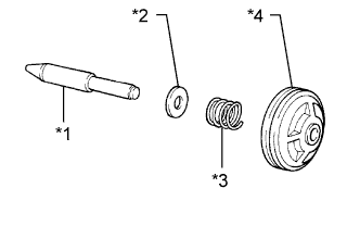
REMOVE PARKING LOCK PAWL
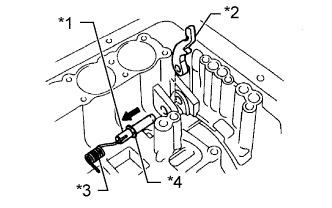
Text in Illustration *1 Parking Lock Pawl Shaft *2 Lock Pawl *3 Spring *4 E-Ring
-
Pull out the parking lock pawl shaft from the front side, and then remove the lock pawl and spring.
-
Remove the E-ring from the shaft.
-
-
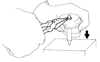
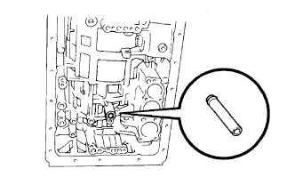
REMOVE MANUAL VALVE LEVER SHAFT
-
Using a hammer and screwdriver, cut off the spacer and remove it from the shaft.
Text in Illustration *1 Spacer -
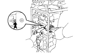
Using a pin punch and hammer, tap out the spring pin.
Tech Tips
Slowly drive out the spring pin so that it does not fall into the transmission case.
-
Pull out the manual valve lever shaft through the case and remove the manual valve lever.
-
-
REMOVE MANUAL VALVE LEVER SHAFT OIL SEAL
-
Using a screwdriver, pry out the 2 oil seals.
-
-
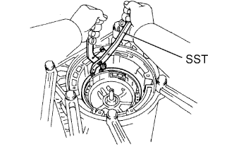
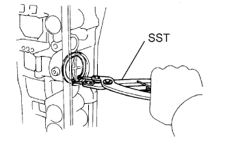
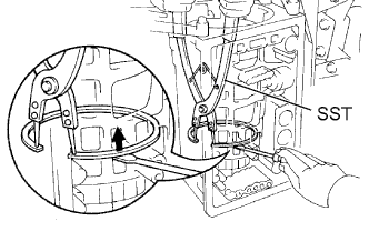
REMOVE OIL PUMP ASSEMBLY
-
Stand the transmission.
-
Remove the 7 bolts from the transmission case.
-
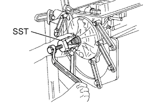
Using SST, remove the oil pump.
- SST
- 09610-20012
-
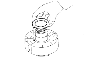
Remove the O-ring from the oil pump.
-
Remove the bearing race from the oil pump.
-
-
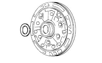
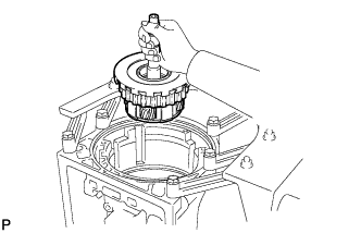
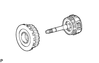
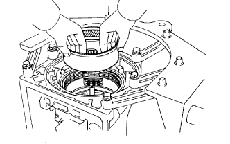
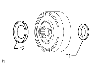
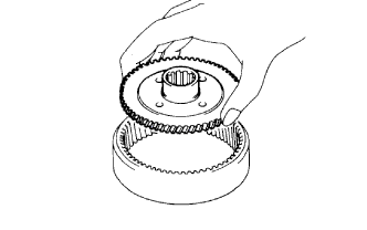
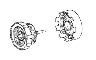
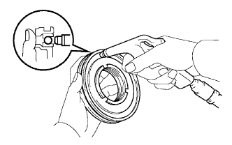
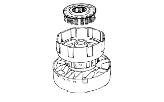
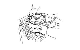
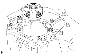
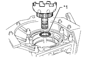
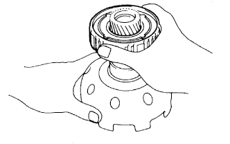
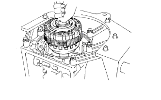
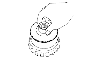
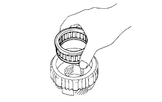
REMOVE OVERDRIVE PLANETARY GEAR ASSEMBLY WITH OVERDRIVE DIRECT CLUTCH AND OVERDRIVE 1-WAY CLUTCH ASSEMBLY
-
Remove the planetary gear with direct clutch and 1-way clutch from the transmission case.
-
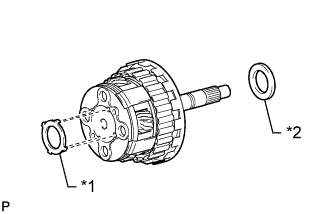
Text in Illustration *1 Bearing Race *2 Bearing Remove the bearing race and bearing.
-
-
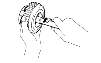
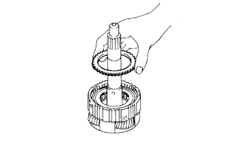
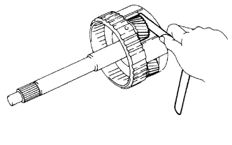
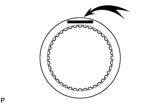
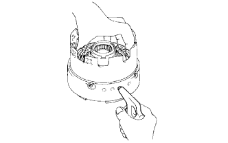
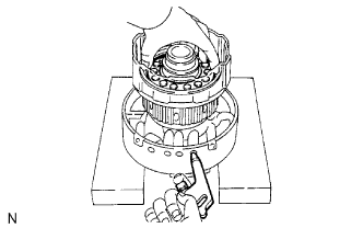
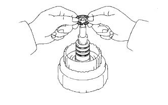
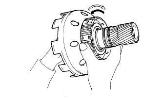
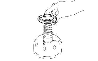
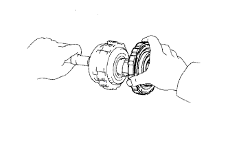
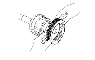
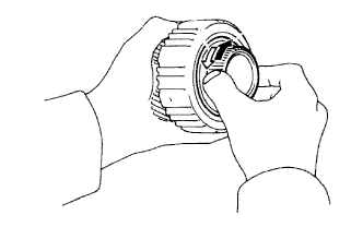
INSPECT OVERDRIVE 1-WAY CLUTCH
-
Hold the overdrive direct clutch drum and turn the input shaft. Check that the input shaft can be turned clockwise freely and locks when turned counterclockwise.
Text in Illustration 
Lock 
Free
-
-
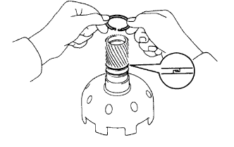
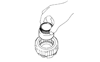
REMOVE OVERDRIVE DIRECT CLUTCH ASSEMBLY
-
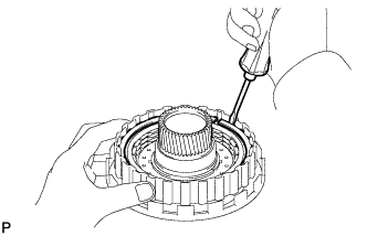
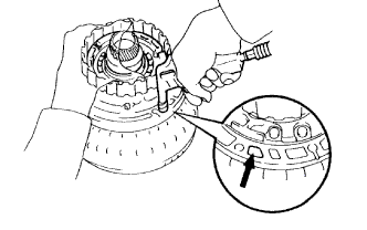
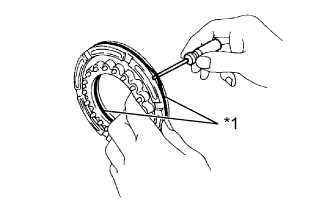
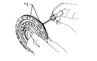
REMOVE OVERDRIVE DIRECT CLUTCH DISC SET
-
Using a screwdriver, pry out the snap ring from the overdrive direct clutch drum.
-
Remove the flange, 2 discs and 2 plates.
-
-
INSPECT OVERDRIVE DIRECT CLUTCH DISC

-
Replace all the discs if one of the following problems is present: 1) a disc, plate or flange is worn or burnt, 2) the lining of a disc is peeled off or discolored, or 3) the grooves or printed numbers have even a little bit of damage.
Note
When assembling new discs, soak them in ATF for at least 15 minutes before assembly.
-
-
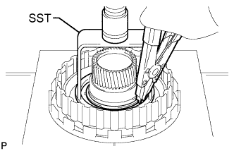
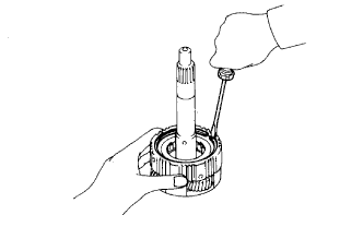
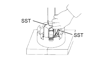
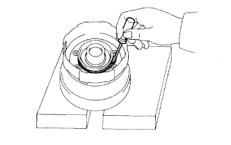
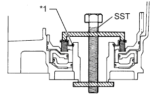
REMOVE OVERDRIVE DIRECT CLUTCH RETURN SPRING SUB-ASSEMBLY
-
Place SST on the spring retainer and compress the return spring with a press.
- SST
- 09350-30020 ( 09350-07040 )
Note
Do not deform the spring sheet. Stop compressing when the spring sheet is lowered to a position 1 to 2 mm (0.0394 to 0.0787 in.) from the snap ring groove.
-
Using snap ring expander, remove the snap ring.
-
Remove the clutch return spring.
-
-
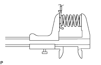
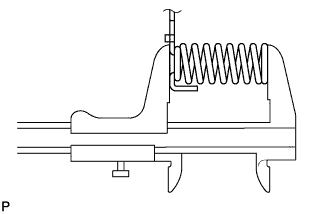
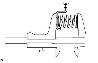
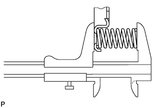
INSPECT OVERDRIVE DIRECT CLUTCH RETURN SPRING SUB-ASSEMBLY
-
Using a vernier caliper, measure the free length of the spring together with the spring seat.
Standard free length 15.8 mm (0.622 in.) If the length is not as specified, replace the overdrive clutch return spring sub-assembly.
-
-
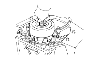
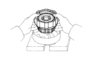
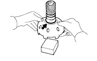
REMOVE OVERDRIVE DIRECT CLUTCH PISTON SUB-ASSEMBLY
-
Place the oil pump onto the torque converter clutch, and then place the overdrive direct clutch onto the oil pump.
-
Hold the overdrive direct clutch piston by hand and apply compressed air (392 kPa (4.0 kgf/cm2, 57 psi)) to the oil pump to remove the overdrive direct clutch piston.
Tech Tips
If the piston is at an angle and cannot be removed, press down on the protruding side and apply compressed air again.
-
Remove the 2 O-rings from the piston.
-
-
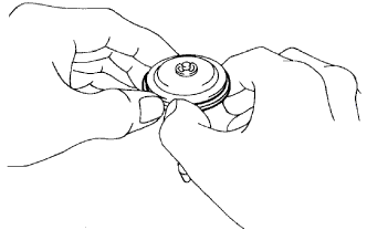
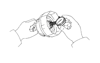
INSPECT OVERDRIVE DIRECT CLUTCH PISTON SUB-ASSEMBLY
-
Check that the check ball is free by shaking the piston.
-
Check that the valve does not have leaks by applying low-pressure compressed air.
If the result is not as specified, replace the overdrive direct clutch piston sub-assembly.
-
-
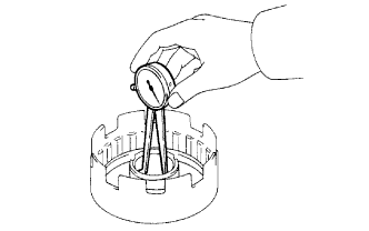
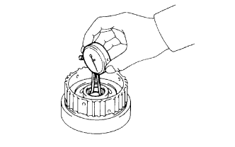
INSPECT OVERDRIVE DIRECT CLUTCH DRUM SUB-ASSEMBLY
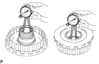
-
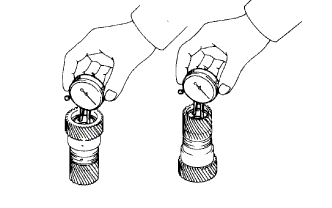
Using a dial indicator, measure the inside diameter of the clutch drum bushes.
Maximum inside diameter 27.11 mm (1.07 in.) If the inside diameter is more than the maximum, replace the overdrive direct clutch drum sub-assembly.
-
-
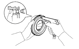
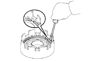
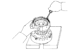
REMOVE OVERDRIVE RETAINING PLATE
-
Using a screwdriver, pry out the snap ring.
-
Remove the retaining plate.
-
-
REMOVE OVERDRIVE 1-WAY CLUTCH OUTER RACE WITH OVERDRIVE 1-WAY CLUTCH
-
REMOVE OVERDRIVE 1-WAY CLUTCH
-
Remove the overdrive 1-way clutch from the outer race.
-
-
REMOVE NO. 3 OVERDRIVE PLANETARY GEAR THRUST WASHER
-
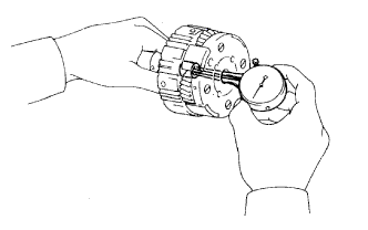
INSPECT OVERDRIVE PLANETARY GEAR ASSEMBLY
-
Using a dial indicator, measure the inside diameter of the planetary gear bush.
Maximum inside diameter 11.2 to 11.221 mm (0.441 to 0.442 in.) If the inside diameter is more than the maximum, replace the overdrive planetary gear assembly.
-
Using a feeler gauge, measure the planetary pinion gear thrust clearance.
Standard clearance 0.20 to 0.60 mm (0.00787 to 0.0236 in.) Maximum clearance 0.65 mm (0.0256 in.) If the clearance is more than the maximum, replace the overdrive planetary gear assembly.
-
-
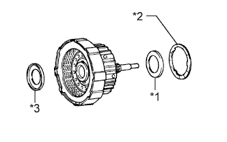
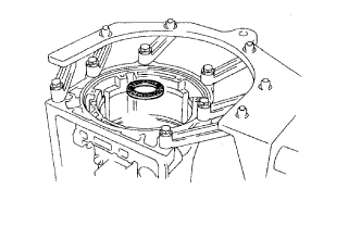
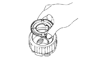
REMOVE OVERDRIVE PLANETARY RING GEAR WITH OVERDRIVE PLANETARY RING GEAR FLANGE
-
Remove the ring gear with the overdrive planetary ring gear flange from the transmission case.
-
Text in Illustration *1 Bearing *2 Bearing Race Remove the bearing and bearing race from the overdrive planetary ring gear.
-
-
REMOVE OVERDRIVE PLANETARY RING GEAR FLANGE
-
Using a screwdriver, pry out the snap ring.
-
Remove the ring gear flange from the overdrive planetary ring gear.
-
-
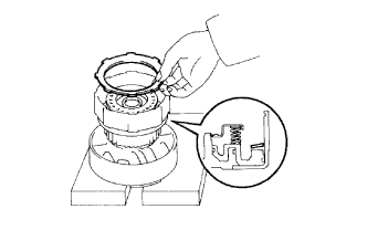
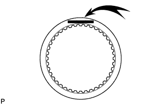
REMOVE OVERDRIVE BRAKE DISC SET
-
Using a screwdriver, pry out the snap ring.
-
Remove the flange, 3 discs and 3 plates from the transmission case.
-
-
INSPECT OVERDRIVE BRAKE DISC

-
Replace all the discs if one of the following problems is present: 1) a disc, plate or flange is worn or burnt, 2) the lining of a disc is peeled off or discolored, or 3) the grooves or printed numbers have even a little bit of damage.
Note
When assembling new discs, soak them in ATF for at least 15 minutes before assembly.
-
-
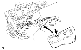
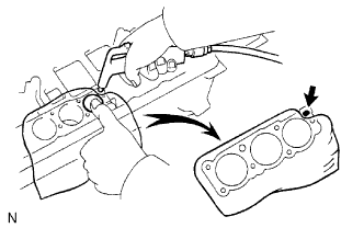
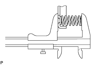
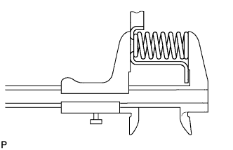
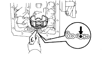
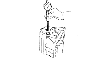
INSPECT PISTON STROKE OF SECOND COAST BRAKE
-
Using a waterproof pen, place a mark on the 2nd coast brake piston rod as shown in the illustration.
Text in Illustration *1 Piston Rod *2 Mark -
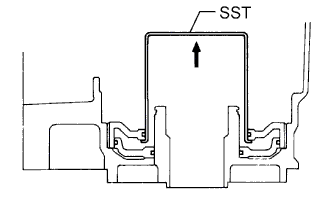
Using SST, measure the piston stroke while applying and releasing compressed air (392 kPa (4.0 kgf/cm2, 57 psi)).
- SST
- 09240-00020
Standard piston stroke 1.5 to 3.0 mm (0.0591 to 0.118 in.) If the stroke is not as specified, inspect the brake band.
-
-
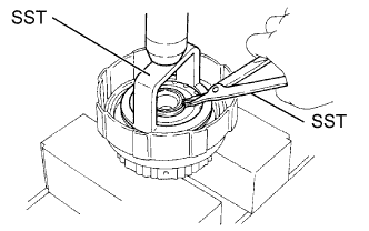
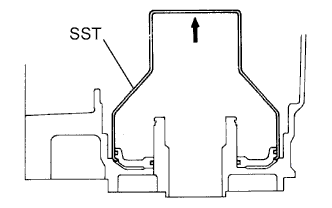
REMOVE OVERDRIVE SUPPORT SUB-ASSEMBLY
-
Remove the 2 bolts holding the overdrive brake assembly to the case.
-
Using SST, remove the snap ring.
- SST
- 09350-30020 ( 09350-07060 )
-
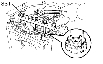
Using SST, remove the overdrive brake assembly.
- SST
- 09350-30020 ( 09350-07020 )
-
Text in Illustration *1 Bearing *2 Bearing Race Remove the bearing and bearing race from the overdrive brake.
-
-
INSPECT PISTON OPERATION OF OVERDRIVE BRAKE
-
Place the overdrive support assembly to the direct clutch assembly.
-
Apply compressed air (392 kPa (4 kgf/cm2, 57 psi)) into the oil passage and check that the overdrive brake piston moves smoothly.
-
-
REMOVE OVERDRIVE BRAKE RETURN SPRING SUB-ASSEMBLY
-
Place SST on the spring retainer and compress the return spring with a press.
- SST
- 09350-30020 ( 09350-07030 )
-
Using a screwdriver, pry out the snap ring.
-
Remove the brake return spring.
-
-
INSPECT OVERDRIVE BRAKE RETURN SPRING SUB-ASSEMBLY
-
Using a vernier caliper, measure the free length of the spring together with the spring seat.
Standard free length 17.03 mm (0.671 in.) If the length is not as specified, replace the overdrive brake return spring sub-assembly.
-
-
REMOVE OVERDRIVE BRAKE PISTON
-
Place the overdrive support onto the direct clutch assembly.
-
Hold the overdrive brake piston so that it is not slanted, and apply compressed air (392 kPa (4 kgf/cm2, 57 psi)) into the passage to remove the overdrive brake piston.
-
Text in Illustration *1 O-Ring Remove the 2 O-rings from the overdrive brake piston.
-
-
REMOVE OVERDRIVE CLUTCH DRUM OIL SEAL RING
-
Remove the 2 oil seal rings from the overdrive support.
-
Remove the clutch drum thrust washer from the overdrive support.
-
-
REMOVE SECOND COAST BRAKE PISTON
-
Using SST, remove the snap ring.
- SST
- 09350-30020 ( 09350-07060 )
-
Apply compressed air to the oil hole to remove the second coast brake cover, piston assembly and spring.
-
Remove the 2 O-rings from the cover.
-
-
REMOVE SECOND COAST BRAKE PISTON OIL SEAL RING
-
REMOVE SECOND COAST BRAKE PISTON ROD
-
Firmly press the piston down to compress the compression spring.
-
Remove the E-ring.
-
Text in Illustration *1 Piston Rod *2 Washer Plate *3 Spring *4 Piston Remove the piston rod, washer plate and spring from the piston.
-
-
REMOVE DIRECT CLUTCH ASSEMBLY WITH FORWARD CLUTCH ASSEMBLY
-
Remove the direct clutch with the forward clutch from the case.
-
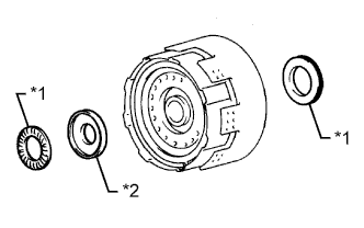
Text in Illustration *1 Bearing *2 Bearing Race Remove the 2 bearings and bearing race.
-
-
REMOVE FORWARD CLUTCH ASSEMBLY
-
Remove the forward clutch from the direct clutch.
-
Text in Illustration *1 Bearing *2 Thrust Washer *3 Bearing Race Remove the bearing, thrust washer and bearing race from the forward clutch.
-
-
REMOVE DIRECT CLUTCH DISC SET
-
Using a screwdriver, pry out the snap ring from the direct clutch drum.
-
Remove the flange, 3 discs and 3 plates.
-
-
INSPECT DIRECT CLUTCH DISC
-
Replace all the discs if one of the following problems is present: 1) a disc, plate or flange is worn or burnt, 2) the lining of a disc is peeled off or discolored, or 3) the grooves or printed numbers have even a little bit of damage.
Note
When assembling new discs, soak them in ATF for at least 15 minutes before assembly.
-
-
REMOVE DIRECT CLUTCH RETURN SPRING SUB-ASSEMBLY
-
Place SST on the spring retainer and compress the return spring with a press.
- SST
- 09350-30020 ( 09350-07040 )
-
Using SST, remove the snap ring.
- SST
- 09350-30020 ( 09350-07070 )
-
Remove the return spring.
-
-
INSPECT DIRECT CLUTCH RETURN SPRING SUB-ASSEMBLY
-
Using a vernier caliper, measure the free length of the spring together with the spring seat.
Standard free length 21.32 mm (0.839 in.) If the length is not as specified, replace the direct clutch return spring sub-assembly.
-
-
REMOVE DIRECT CLUTCH PISTON SUB-ASSEMBLY
-
Place the direct clutch drum on the overdrive support.
-
Hold the direct clutch piston and apply compressed air (196 kPa (2.0 kgf/cm2, 28.5 psi)) to the overdrive support to remove the direct clutch piston.
Tech Tips
Make sure the direct clutch piston is not tilted before applying compressed air.
-
Text in Illustration *1 O-Ring Using a small screwdriver, remove the 2 O-rings from the piston.
-
-
INSPECT DIRECT CLUTCH PISTON SUB-ASSEMBLY
-
Check that the check ball is free by shaking the piston.
-
Check that the valve does not have leaks by applying low-pressure compressed air.
-
-
INSPECT DIRECT CLUTCH DRUM SUB-ASSEMBLY
-
Using a dial indicator, measure the inside diameter of the clutch drum bush.
Standard inside diameter 53.915 to 53.94 mm (2.123 to 2.124 in.) Maximum inside diameter 53.99 mm (2.13 in.) If the inside diameter is more than the maximum, replace the direct clutch drum sub-assembly.
-
-
FIX FORWARD CLUTCH ASSEMBLY
-
Place the overdrive support on wooden blocks or equivalent to prevent the forward clutch shaft from touching the work stand.
-
Place the forward clutch on the overdrive support.
-
-
REMOVE FORWARD CLUTCH DISC SET
-
Using a screwdriver, pry out the snap ring from the forward clutch drum.
-
Remove the flange, 6 discs and 6 plates.
-
Remove the cushion plate.
-
-
INSPECT FORWARD CLUTCH DISC
-
Replace all the discs if one of the following problems is present: 1) a disc, plate or flange is worn or burnt, 2) the lining of a disc is peeled off or discolored, or 3) the grooves or printed numbers have even a little bit of damage.
Note
When assembling new discs, soak them in ATF for at least 15 minutes before assembly.
-
-
REMOVE FORWARD CLUTCH RETURN SPRING SUB-ASSEMBLY
-
Place SST on the spring retainer and compress the return spring with a press.
- SST
- 09350-30020 ( 09350-07040 )
-
Using SST, remove the snap ring.
- SST
- 09350-30020 ( 09350-07070 )
-
Remove the piston return spring.
-
-
INSPECT FORWARD CLUTCH RETURN SPRING SUB-ASSEMBLY
-
Using a vernier caliper, measure the free length of the spring together with the spring seat.
Standard free length 19.47 mm (0.767 in.) If the length is not as specified, replace the forward clutch return spring sub-assembly.
-
-
REMOVE FORWARD CLUTCH PISTON SUB-ASSEMBLY
-
Place the forward clutch drum onto the overdrive support.
-
Hold the forward clutch piston by hand and apply compressed air (196 kPa (2.0 kgf/cm2, 28.5 psi)) to the overdrive support to remove the forward clutch piston.
-
Remove the O-ring from the forward clutch drum.
-
Text in Illustration *1 O-Ring Remove the 2 O-rings from the forward clutch piston.
-
-
INSPECT FORWARD CLUTCH PISTON SUB-ASSEMBLY
-
Check that the check ball is free by shaking the piston.
-
Check that the valve does not have leaks by applying low-pressure compressed air.
-
-
REMOVE INPUT SHAFT OIL SEAL RING
-
Remove the 3 oil seal rings from the forward clutch drum groove.
-
-
INSPECT INPUT SHAFT SUB-ASSEMBLY
-
Using a dial indicator, measure the inside diameter of the input shaft bush.
Standard inside diameter 24.0 to 24.026 mm (0.945 to 0.946 in.) Maximum inside diameter 24.076 mm (0.948 in.) If the inside diameter is more than the maximum, replace the input shaft sub-assembly.
-
-
REMOVE SECOND COAST BRAKE BAND ASSEMBLY
-
Using a screwdriver, pry of the 2 E-rings from the pin, and pull out the pin.
-
Remove the 2nd coast brake band from the case.
-
-
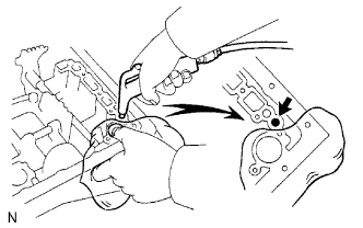
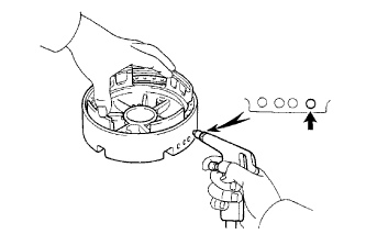
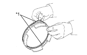
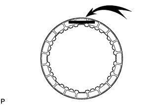
INSPECT SECOND COAST BRAKE BAND ASSEMBLY
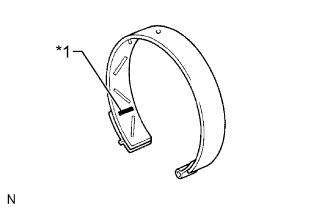
Text in Illustration *1 Printed Number Note
-
If the lining of the brake band is peeled off or discolored, or if any part of the printed numbers are damaged, replace the brake band.
-
When installing a new band, soak it in ATF for at least 15 minutes before installation.
-
-
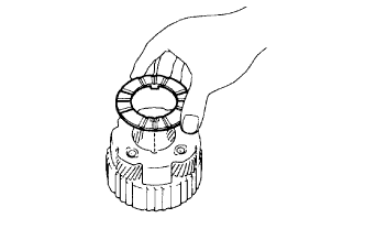
REMOVE FRONT PLANETARY RING GEAR SUB-ASSEMBLY
-
Remove the planetary ring gear from the case.
-
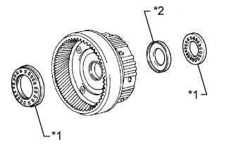
Text in Illustration *1 Bearing *2 Bearing Race Remove the 2 bearing and bearing race from the planetary ring gear.
-
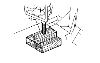
Text in Illustration *1 Wooden Block Place the output shaft on wooden blocks or equivalent.
-
-
INSPECT FRONT PLANETARY RING GEAR SUB-ASSEMBLY
-
Using a dial indicator, measure the inside diameter of the planetary ring gear bush.
Standard inside diameter 24.0 to 24.026 mm (0.945 to 0.946 in.) Maximum inside diameter 24.076 mm (0.948 in.) If the inside diameter is more than the maximum, replace the front planetary ring gear sub-assembly.
-
-
REMOVE FRONT PLANETARY GEAR ASSEMBLY
-
Remove the bearing race from the planetary gear.
-
Using SST, remove the snap ring.
- SST
- 09350-30020 ( 09350-07070 )
-
Remove the planetary gear from the case.
-
Remove the bearing and bearing race from the planetary gear.
-
-
INSPECT FRONT PLANETARY GEAR ASSEMBLY
-
Using a feeler gauge, measure the pinion gear thrust clearance.
Standard clearance 0.20 to 0.60 mm (0.00787 to 0.0236 in.) Maximum clearance 0.65 mm (0.0256 in.) If the clearance is more than the maximum, replace the front planetary gear assembly.
-
-
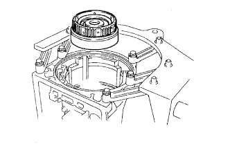
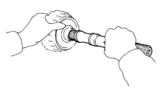
REMOVE PLANETARY SUN GEAR SUB-ASSEMBLY WITH SUN GEAR INPUT DRUM AND NO. 1 1-WAY CLUTCH ASSEMBLY
Text in Illustration *1 Thrust Washer
-
Remove the sun gear with the sun gear input drum and 1-way clutch from the case.
-
Remove the thrust washer.
-
-
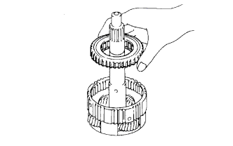
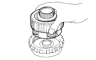
INSPECT NO. 1 1-WAY CLUTCH ASSEMBLY
-
Hold the planetary sun gear, and turn the 1-way clutch assembly. Check that the 1-way clutch hub can be turned clockwise freely and locks when turned counterclockwise.
Text in Illustration Lock Free
-
-
REMOVE NO. 1 1-WAY CLUTCH ASSEMBLY
-
REMOVE NO. 1 1-WAY CLUTCH THRUST WASHER
-
REMOVE SUN GEAR SHAFT OIL SEAL RING
-
Remove the 2 oil seal rings from the sun gear input drum.
-
-
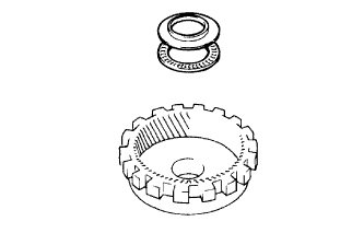
REMOVE SUN GEAR INPUT DRUM
-
Place the planetary sun gear onto a wooden block or similar object.
-
Using snap ring pliers, remove the snap ring.
-
Remove the input drum from the planetary sun gear.
-
-
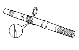
REMOVE SUN GEAR INPUT DRUM SHAFT SNAP RING
-
Using a screwdriver, pry off the snap ring from the planetary sun gear.
-
-
INSPECT PLANETARY SUN GEAR SUB-ASSEMBLY
-
Using a dial indicator, measure the inside diameter of the planetary sun gear bushes.
Standard inside diameter 27.00 to 27.026 mm (1.063 to 1.064 in.) Maximum inside diameter 27.076 mm (1.07 in.) If the inside diameter is more than the maximum, replace the planetary sun gear sub-assembly.
-
-
REMOVE SECOND BRAKE DISC SET
-
Using a screwdriver, pry out the snap ring.
-
Remove the 2 flange, 5 discs and 4 plates.
-
-
REMOVE SECOND BRAKE PISTON SLEEVE
-
Using a screwdriver, remove the sleeve.
-
-
REMOVE OUTPUT SHAFT WITH REAR PLANETARY GEAR, NO. 2 1-WAY CLUTCH, FIRST AND REVERSE BRAKE DISC SET AND SECOND BRAKE DRUM
-
Using SST and a screwdriver, remove the snap ring.
- SST
- 09350-30020 ( 09350-07060 )
-
Remove the output shaft with the rear planetary gear, No. 2 1-way clutch, first and reverse brake disc set and second brake drum from transmission case.
-
Remove the thrust bearing from the transmission case.
-
-
REMOVE SECOND BRAKE DRUM SUB-ASSEMBLY
-
Remove the second brake drum.
-
-
REMOVE NO. 4 PLANETARY CARRIER THRUST WASHER
-
INSPECT SECOND BRAKE PISTON
-
Check that the second brake piston moves smoothly when applying compressed air to and releasing low-pressure compressed air from the second brake drum.
-
-
REMOVE SECOND BRAKE PISTON RETURN SPRING SUB-ASSEMBLY
-
Place SST on the spring retainer and compress the piston return spring with a press.
- SST
- 09350-30020 ( 09350-07040 )
-
Using a snap ring expander, remove the snap ring.
Note
-
Do not deform the spring sheet. Stop compressing when the spring sheet is lowered to a position 1 to 2 mm (0.0394 to 0.0787 in.) from the snap ring groove.
-
Do not expand the snap ring excessively.
-
-
Remove the second brake piston return spring seat.
-
Remove the piston return spring.
-
-
INSPECT SECOND BRAKE PISTON RETURN SPRING SUB-ASSEMBLY
-
Using a vernier caliper, measure the free length of the spring together with the spring seat.
Standard free length 16.05 mm (0.632 in.) If the length is not as specified, replace the second brake piston return spring sub-assembly.
-
-
REMOVE SECOND BRAKE PISTON
-
Hold the second brake piston by hand and apply compressed air to the 2nd brake drum to remove the 2nd brake piston.
Tech Tips
If the piston is at an angle and cannot be removed, press down on the protruding side and apply compressed air again.
-
Remove the 2 O-rings from the piston.
-
-
REMOVE FIRST AND REVERSE BRAKE DISC SET
-
Remove the flange, 6 plates and 6 discs.
-
-
INSPECT FIRST AND REVERSE BRAKE DISC
-
Replace all the discs if one of the following problems is present: 1) a disc, plate or flange is worn or burnt, 2) the lining of a disc is peeled off or discolored, or 3) the grooves or printed numbers have even a little bit of damage.
Note
When assembling new discs, soak them in ATF for at least 15 minutes before assembly.
-
-
REMOVE OUTPUT SHAFT
-
REMOVE PLANETARY OUTPUT SHAFT OIL SEAL RING
-
REMOVE REAR PLANETARY RING GEAR
-
Remove the rear planetary gear from the planetary ring gear.
-
Remove the 2 bearing race and bearing from the planetary ring gear.
-
Using a screwdriver, pry out the snap ring.
-
Remove the planetary ring gear flange.
-
-
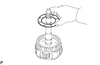
INSPECT NO. 2 1-WAY CLUTCH
-
Hold the planetary gear and turn the 1-way clutch inner race. Check that the 1-way clutch inner race can be turned counterclockwise freely and locks when turned clockwise.
Text in Illustration Lock Free
-
-
REMOVE NO. 2 1-WAY CLUTCH
-
Remove the 1-way clutch inner race from the planetary gear.
-
Using a screwdriver, pry out the snap ring.
-
Remove the 1-way clutch from the planetary gear.
-
Remove the No. 2 planetary carrier thrust washer from the planetary gear.
-
Remove the No. 1 planetary carrier thrust washer from the planetary gear.
-
-
INSPECT REAR PLANETARY GEAR ASSEMBLY
-
Using a feeler gauge, measure the thrust clearance.
Standard clearance 0.20 to 0.60 mm (0.00797 to 0.0236 in.) Maximum clearance 0.65 mm (0.0256 in.) If the clearance is more than the maximum, replace the rear planetary gear assembly.
-
-
REMOVE LEAF SPRING
-
REMOVE BRAKE DRUM GASKET
-
REMOVE FIRST AND REVERSE BRAKE RETURN SPRING SUB-ASSEMBLY
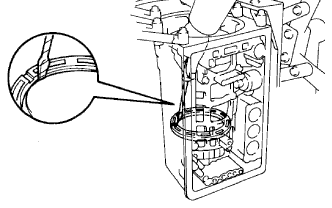
Text in Illustration *1 Snap Ring
-
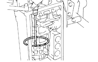
Place SST on the first and reverse brake return spring and compress the brake return spring.
- SST
- 09350-30020 ( 09350-07050 )
-
Using SST, remove the snap ring and brake return spring.
- SST
- 09350-30020 ( 09350-07070 )
-
-
INSPECT 1ST AND REVERSE BRAKE RETURN SPRING SUB-ASSEMBLY
-
Using a vernier caliper, measure the free length of the spring together with the spring seat.
Standard free length 18.182 to 18.582 mm (0.716 to 0.732 in.) If the length is not as specified, replace the first and reverse brake return spring sub-assembly.
-
-
REMOVE NO. 2 FIRST AND REVERSE BRAKE PISTON
-
Hold the No. 2 first and reverse brake piston and apply compressed air to the transmission case to remove the brake piston.
Tech Tips
If the piston does not pop out with compressed air, lift the piston out with needle-nose pliers.
-
Remove the O-ring from the brake piston.
-
-
REMOVE BRAKE REACTION SLEEVE
-
Using SST, remove the sleeve.
- SST
- 09350-30020 ( 09350-07080 )
-
Remove the O-rings from the sleeve.
-
-
REMOVE NO. 1 1ST AND REVERSE BRAKE PISTON
-
Using SST, remove the brake piston.
- SST
- 09350-30020 ( 09350-07090 )
-
Remove the 2 O-rings from the brake piston.
-
-
INSPECT TRANSMISSION CASE BUSH
-
Using a cylinder gauge, measure the inside diameter of the transmission case rear bush.
Standard inside diameter 38.113 to 38.138 mm (1.5005 to 1.5014 in.) Maximum inside diameter 38.19 mm (1.50 in.) If the inside diameter is more than the maximum, replace the automatic transmission case sub-assembly.
-