AUTOMATIC TRANSMISSION SYSTEM TERMINALS OF ECM

-
CHECK ECM
Tech Tips
The standard voltage at each ECM terminal is shown in the table below.
In the table, first follow the information under "Condition". Look under "Terminal No. (Symbol)" for the terminals to inspect. The standard voltage between the terminals is shown under "Specified Condition".
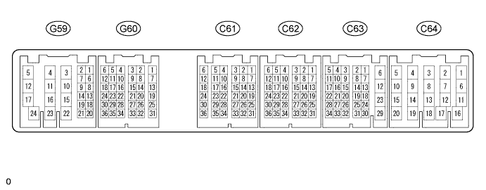
Use the illustration above as a reference for the ECM terminals.
Terminal No. (Symbol) Wiring Color Terminal Description Condition Specified Condition G60-24 (NSW) - C64-5 (E1) B - BR PNP switch signal
-
Ignition switch ON
-
Shift lever in P or N
Below 1 V
-
Ignition switch ON
-
Shift lever not in P or N
11 to 14 V C63-16 (P) - C64-5 (E1) L - BR P shift position switch signal
-
Ignition switch ON
-
Shift lever in P
11 to 14 V
-
Ignition switch ON
-
Shift lever not in P
Below 1 V C63-17 (R) - C64-5 (E1) R - BR R shift position switch signal
-
Ignition switch ON
-
Shift lever in R
11 to 14 V
-
Ignition switch ON
-
Shift lever not in R
Below 1 V C63-11 (N) - C64-5 (E1) G - BR N shift position switch signal
-
Ignition switch ON
-
Shift lever in N
11 to 14 V
-
Ignition switch ON
-
Shift lever not in N
Below 1 V G60-9 (D) - C64-5 (E1) B - BR D shift position switch signal
-
Ignition switch ON
-
Shift lever in D or 3
11 to 14 V
-
Ignition switch ON
-
Shift lever not in D or 3
Below 1 V G60-23 (3) - C64-5 (E1) V - BR 3 shift position switch signal
-
Ignition switch ON
-
Shift lever in 3
11 to 14 V
-
Ignition switch ON
-
Shift lever not in 3
Below 1 V C63-15 (2) - C64-5 (E1) P - BR 2 shift position switch signal
-
Ignition switch ON
-
Shift lever in 2
11 to 14 V
-
Ignition switch ON
-
Shift lever not in 2
Below 1 V C63-25 (L) - C64-5 (E1) W - BR L shift position switch signal
-
Ignition switch ON
-
Shift lever in L
11 to 14 V
-
Ignition switch ON
-
Shift lever not in L
Below 1 V C62-21 (S1) - C64-5 (E1) B-W - BR S1 solenoid signal 1st or 2nd gear 11 to 14 V 3rd or 4th gear Below 1 V C62-22 (S2) - C64-5 (E1) B-R - BR S2 solenoid signal 2nd or 3rd gear 11 to 14 V 1st or 4th gear Below 1 V C62-23 (SLT+) - C62-24 (SLT-) G-B - L-B SLT solenoid signal Engine idling Pulse generation
(See waveform 1)
C63-20 (SLU+) - C63-21 (SLU-) P - LG SLU solenoid signal 3rd gear (lock-up) or 4th gear (lock-up) Pulse generation
(See waveform 2)
C62-18 (THO1) - C62-17 (ETHO) L - R No. 1 ATF temperature sensor signal No. 1 ATF temperature: 115°C (239°F) or higher Below 1.5 V C61-2 (THOC) - C62-16 (E2) W-L - W-R No. 2 ATF temperature sensor signal No. 2 ATF temperature: 115°C (239°F) or higher Below 1.5 V C63-2 (SP2+) - C63-9 (SP2-) B - W Speed sensor SP2 signal Vehicle speed 20 km/h (12 mph) Pulse generation
(See waveform 3)
C63-5 (NCO+) - C63-10 (NCO-) L - W Speed sensor NCO signal Engine idling
(shift lever in P or N)
Pulse generation
(See waveform 4)
G59-14 (L4) - C64-5 (E1) R - BR L4 position signal
-
Ignition switch ON
-
Transfer in L4
Below 1 V
-
Ignition switch ON
-
Transfer not in L4
11 to 14 V G60-34 (CANH) - C64-5 (E1) LG - BR CAN communication line Ignition switch ON Pulse generation
(See waveform 5)
G60-33 (CANL) - C64-5 (E1) W - BR CAN communication line Ignition switch ON Pulse generation
(See waveform 6)
G60-27 (SNWI) - C64-5 (E1) GR - BR Pattern select (2ND) switch signal
-
Ignition switch ON
-
Pattern select (2ND) switch pushed
Below 1 V
-
Ignition switch ON
-
Pattern select (2ND) switch not pushed
11 to 14 V
-
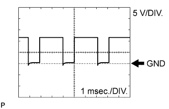
Using an oscilloscope, check waveform 1.
Reference Terminal No. (Symbol) Tool Setting Condition C62-23 (SLT+) - C62-24 (SLT-) 5 V/DIV., 1 msec./DIV. Engine idling -
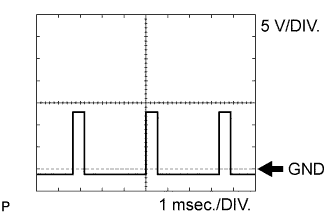
Using an oscilloscope, check waveform 2.
Reference Terminal No. (Symbol) Tool Setting Condition C63-20 (SLU+) - C63-21 (SLU-) 5 V/DIV., 1 msec./DIV. 3rd gear (lock-up) or 4th gear (lock-up) -
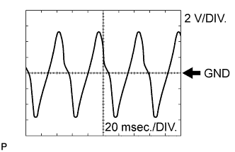
Using an oscilloscope, check waveform 3.
Reference Terminal No. (Symbol) Tool Setting Condition C63-2 (SP2+) - C63-9 (SP2-) 2 V/DIV., 20 msec./DIV. Vehicle speed 20 km/h (12 mph) -
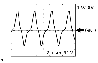
Using an oscilloscope, check waveform 4.
Reference Terminal No. (Symbol) Tool Setting Condition C63-5 (NCO+) - C63-10 (NCO-) 1 V/DIV., 2 msec./DIV. Engine idling (shift lever in P or N) -
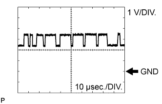
Using an oscilloscope, check waveform 5.
Reference Terminal No. (Symbol) Tool Setting Condition G60-34 (CANH) - C64-5 (E1) 1 V/DIV., 10 μsec./DIV. Ignition switch ON -
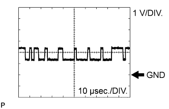
Using an oscilloscope, check waveform 6.
Reference Terminal No. (Symbol) Tool Setting Condition G60-33 (CANL) - C64-5 (E1) 1 V/DIV., 10 μsec./DIV. Ignition switch ON
-