DRIVING SUPPORT ECU INSTALLATION

Note
-
Do not twist the connectors of the driving support ECU when connecting them.
-
Do not apply more force than necessary to the connectors. If more than 98 N (10 kgf, 22 lbf) of force is applied to a connector, the connector or connector holder may be damaged.
Tech Tips
-
A bolt without a torque specification is shown in the standard bolt chart Click here.
-
Use the same procedure for RHD and LHD vehicles.
-
The procedure listed below is for LHD vehicles.
-
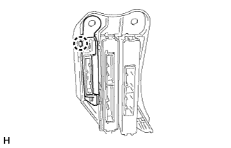
INSTALL DRIVING SUPPORT ECU ASSEMBLY
-
Attach the claw to install the driving support ECU assembly.
Note
When a new ECU is installed, perform initialization Click here.
-
-
INSTALL ECU INTEGRATION BOX RH
-
Install the ECU integration box RH with the 2 nuts and bolt.
-
Attach the clamp.
-
Connect the connectors.
-
-
INSTALL NO. 2 AIR DUCT SUB-ASSEMBLY
-
Attach the 2 claws to install the No. 2 air duct sub-assembly.
-
Install the screw.
-
-
INSTALL GLOVE COMPARTMENT DOOR ASSEMBLY
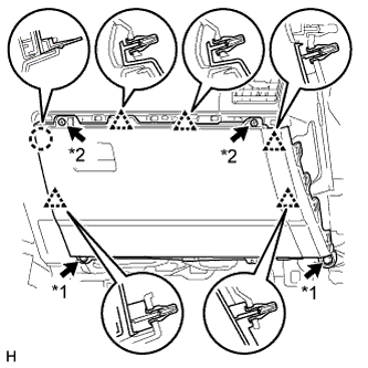
Text in Illustration *1 Bolt *2 Screw
-
Connect each connector.
-
Attach the 5 clips and claw to install the glove compartment door.
-
Install the 2 bolts <C> and 2 screws <A> or <B>.
-
-
INSTALL NO. 2 INSTRUMENT PANEL UNDER COVER SUB-ASSEMBLY
-
Attach the 3 clips and 2 guides to install the No. 2 instrument panel under cover.
-
Install the screw.
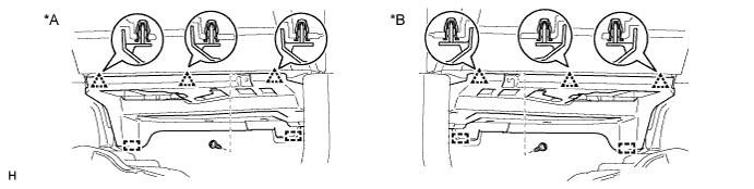
Text in Illustration *A for LHD *B for RHD
-
-
INSTALL INSTRUMENT PANEL ORNAMENT
-
Attach the 5 clips to install the instrument panel ornament.
-
-
INSTALL INSTRUMENT SIDE PANEL RH
-
Connect the connector.
-
Attach the 5 clips, claw and 3 guides to install the instrument side panel.
-
-
INSTALL COWL SIDE TRIM BOARD RH
Tech Tips
Use the same procedure described for the LH side.
-
INSTALL DOOR SCUFF PLATE ASSEMBLY RH
Tech Tips
Use the same procedure described for the LH side.