OIL PUMP INSTALLATION

-
INSTALL WATER PUMP ASSEMBLY
-
Install a new gasket and the water pump with the 8 bolts.
- Torque:
- 9.0 N*m { 91 kgf*cm, 79 in.*lbf }
-
-
INSTALL TIMING CHAIN COVER SUB-ASSEMBLY
-
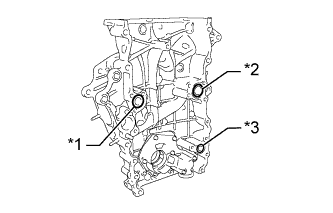
Text in Illustration *1 New Water Pump O-ring *2 New Water Pump Upper O-ring *3 New Oil Pump O-ring Install 3 new O-rings to the timing chain cover as shown in the illustration.
-
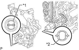
Text in Illustration *1 Drive Rotor Spline *2 Crankshaft Timing Gear Align the drive rotor spline of the oil pump and crankshaft timing gear as shown in the illustration.
-
Apply seal packing to the timing chain cover in a continuous line as shown in the following illustration.
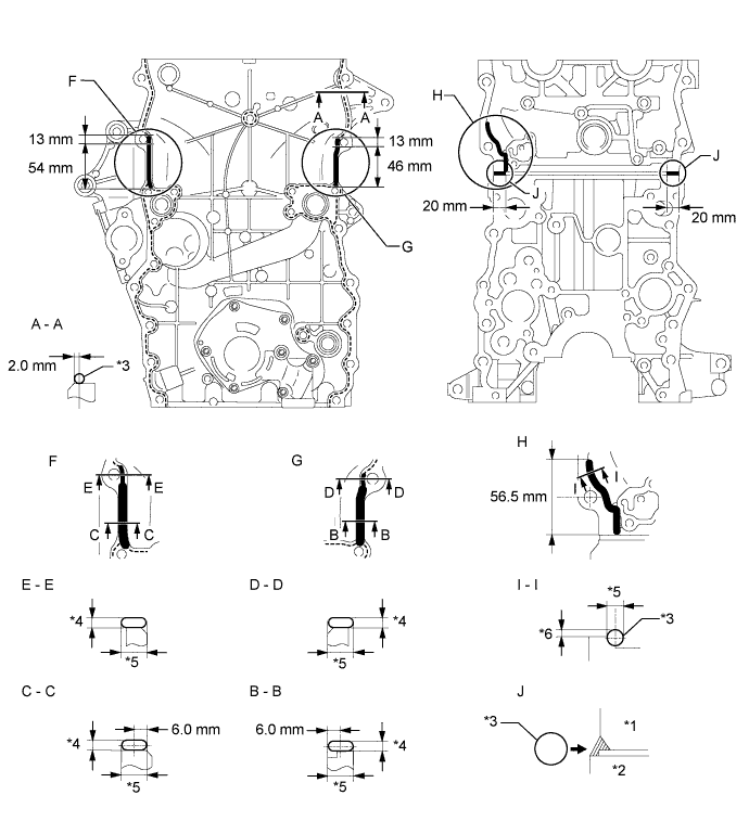
Seal packing Toyota Genuine Seal Packing Black, Three Bond 1207B or equivalent Application Specification Area Seal Packing Diameter Distance from Edge of Cover to Center of Seal Packing Seal Packing Application Length Protrusion from Cylinder Head A - A
(Dashed line)
2.5 to 4.0 mm (0.0984 to 0.157 in.) 2.0 mm (0.0787 in.) - - B - B
(Continuous line)
10 to 14 mm (0.394 to 0.551 in.) wide and 2.5 to 4.0 mm (0.0984 to 0.157 in.) thick 6.0 mm (0.236 in.) 46 mm (1.81 in.) from top of bolt hole - C - C
(Continuous line)
10 to 14 mm (0.394 to 0.551 in.) wide and 2.5 to 4.0 mm (0.0984 to 0.157 in.) thick 6.0 mm (0.236 in.) 54 mm (2.13 in.) from top of bolt hole - D - D
(Continuous line)
9.0 to 13 mm (0.354 to 0.512 in.) wide and 2.5 to 4.0 mm (0.0984 to 0.157 in.) thick - 13 mm (0.512 in.) from top of bolt hole - E - E
(Continuous line)
9.0 to 13 mm (0.354 to 0.512 in.) wide and 2.5 to 4.0 mm (0.0984 to 0.157 in.) thick - 13 mm (0.512 in.) from top of bolt hole - I - I
(Continuous line)
8.0 mm (0.315 in.) - 56.5 mm (2.22 in.) from bottom of cylinder head 2.0 to 3.0 mm (0.0787 to 0.118 in.) J 10 mm (0.394 in.) - 20 mm (0.787 in.) - Text in Illustration *1 Cylinder Head *2 Cylinder Block *3 Seal Packing *4 Seal Packing Thickness *5 Seal Packing Width *6 Protrusion Note
-
Remove any oil from the contact surface.
-
When the contact surfaces are wet, wipe them with an oil-free cloth before applying seal packing.
-
Install the timing chain cover within 3 minutes and tighten the bolts within 15 minutes after applying seal packing.
-
Do not start the engine for at least 4 hours after the installation.
-
-
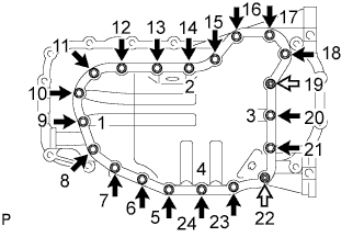
Temporarily install the timing chain cover with the 19 bolts and 2 nuts.
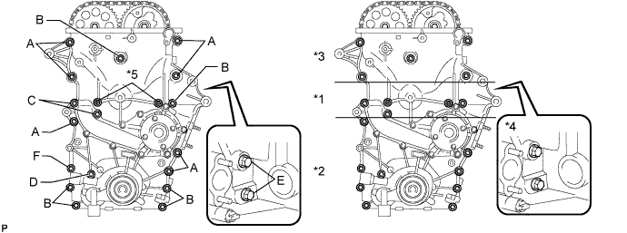
Bolt Length Item Length Thread Diameter Bolt A 75 mm (2.95 in.) 10 mm (0.394 in.) Bolt B 75 mm (2.95 in.) 8 mm (0.315 in.) Bolt C 90 mm (3.54 in.) 8 mm (0.315 in.) Bolt D 95 mm (3.74 in.) 8 mm (0.315 in.) Bolt E 35 mm (1.38 in.) 8 mm (0.315 in.) Bolt F 75 mm (2.95 in.) 10 mm (0.394 in.) -
Excluding the bolts labeled A and F, tighten the bolts and nuts in this order: Area 1, Area 3, Area 2.
- Torque:
- for bolt C
- 26 N*m { 265 kgf*cm, 19 ft.*lbf }
- for bolt B, D and nut
- 21 N*m { 214 kgf*cm, 15 ft.*lbf }
Text in Illustration *1 Area 1 *2 Area 2 *3 Area 3 *4 Area 4 *5 Nut - - -
Tighten the bolts labeled A in this order: Area 2 and Area 3.
- Torque:
- 60 N*m { 612 kgf*cm, 44 ft.*lbf }
-
Tighten the bolts labeled F.
- Torque:
- 46 N*m { 469 kgf*cm, 34 ft.*lbf }
-
Tighten the bolts labeled E in Area 4.
- Torque:
- 21 N*m { 214 kgf*cm, 15 ft.*lbf }
-
-
INSTALL V-RIBBED BELT TENSIONER ASSEMBLY
-
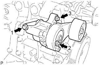
Temporarily install the belt tensioner with the 3 bolts.
Tech Tips
Make sure that the flanges of the bolts are contacting the tensioner surface.
-
Install the tensioner by tightening the 3 bolts in the order shown in the illustration.
- Torque:
- for bolt 1
- 40 N*m { 408 kgf*cm, 30 ft.*lbf }
- for bolt 2
- 21 N*m { 214 kgf*cm, 15 ft.*lbf }
- for bolt 3
- 43 N*m { 438 kgf*cm, 32 ft.*lbf }
-
-
INSTALL OIL PAN SUB-ASSEMBLY
-
Install a new O-ring.
-
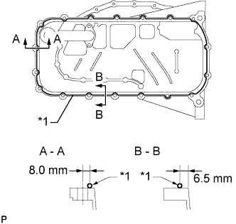
Text in Illustration *1 Seal Packing Apply seal packing in a continuous line as shown in the illustration.
Seal packing Toyota Genuine Seal Packing Black, Three Bond 1207B or equivalent Application Specification Area Seal Packing Diameter Distance from Edge of Cover or Center of Bolt Hole to Center of Seal Packing A - A 2.0 to 3.0 mm (0.0787 to 0.118 in.) 8.0 mm (0.315 in.) B - B 2.0 to 3.0 mm (0.0787 to 0.118 in.) 6.5 mm (0.256 in.) Note
-
Remove any oil from the contact surface.
-
Install the oil pan within 3 minutes after applying seal packing.
-
Do not start the engine for at least 4 hours after the installation.
-
-
Temporarily install the oil pan with the 16 bolts and 2 nuts.
Bolt Length Item Length Bolt A 20 mm (0.787 in.) Bolt B 40 mm (1.57 in.) Text in Illustration 
Bolt A 
Bolt B 
Nut -
Uniformly tighten the 16 bolts and 2 nuts in the order shown in the illustration.
- Torque:
- 26 N*m { 265 kgf*cm, 19 ft.*lbf }
-
-
INSTALL OIL STRAINER SUB-ASSEMBLY
-
Install a new gasket and the oil strainer with the bolt and 2 nuts.
- Torque:
- 26 N*m { 265 kgf*cm, 19 ft.*lbf }
-
-
INSTALL NO. 2 OIL PAN SUB-ASSEMBLY
-
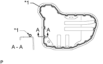
Text in Illustration *1 Seal Packing Apply seal packing in a continuous line as shown in the illustration.
Seal packing Toyota Genuine Seal Packing Black, Three Bond 1207B or equivalent Seal packing diameter 3.0 to 4.0 mm (0.118 to 0.157 in.) Note
-
Remove any oil from the contact surface.
-
Install the oil pan within 3 minutes after applying seal packing.
-
Do not start the engine for at least 4 hours after the installation.
-
-
Temporarily install the oil pan with the 20 bolts and 2 nuts.
Text in Illustration Bolt Nut -
Uniformly tighten the 20 bolts and 2 nuts in the order shown in the illustration.
- Torque:
- 9.0 N*m { 92 kgf*cm, 80 in.*lbf }
-
Install a new gasket and the drain plug.
- Torque:
- 38 N*m { 382 kgf*cm, 28 ft.*lbf }
-
-
INSTALL TIMING CHAIN COVER OIL SEAL
-
Apply MP grease to the lip of a new oil seal.
Note
-
Do not allow foreign matter to contact the lip of the oil seal.
-
Do not allow MP grease to contact the dust seal.
-
-
Temporarily install the oil seal to the timing chain cover.
-
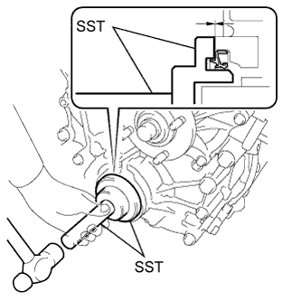
Using SST and a hammer, tap in the oil seal until its surface is flush with the chain cover edge.
- SST
- 09223-75010
- 09950-70010 ( 09951-07100 )
Note
-
Keep the lip free from foreign matter.
-
Do not tap the oil seal at an angle.
-
-
INSTALL CRANKSHAFT PULLEY
-
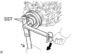
Text in Illustration *a Hold 
Turn Align the key groove of the pulley with the pulley set key and slide on the pulley.
-
Using SST, install a new crankshaft pulley bolt.
- SST
- 09213-54015 ( 91651-60855 )
- 09330-00021
- Torque:
- 260 N*m { 2651 kgf*cm, 192 ft.*lbf }
Note
Do not reuse the pulley bolt.
-
-
INSTALL CYLINDER HEAD COVER SUB-ASSEMBLY
-
Install 2 new cover gaskets to the head cover.
-
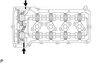
Apply seal packing to the places shown in the illustration.
Seal packing Toyota Genuine Seal Packing Black, Three Bond 1207B or equivalent Seal packing diameter 4.0 mm (0.157 in.) Text in Illustration Seal Packing Note
-
Remove any oil from the contact surface.
-
Install the head cover within 3 minutes after applying seal packing.
-
Do not start the engine for at least 4 hours after the installation.
-
-
Temporarily install the head cover with the 19 bolts and 2 nuts.
-
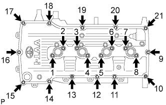
Uniformly tighten the 19 bolts and 2 nuts in the order shown in the illustration.
- Torque:
- 9.0 N*m { 92 kgf*cm, 80 in.*lbf }
-
In numerical order, confirm that the bolts labeled 1 to 8 are tightened to the specified torque. Tighten the bolts as necessary.
-
-
INSTALL NO. 1 WATER BY-PASS PIPE
-
Install a new gasket and the water by-pass pipe with the 2 nuts and bolt.
- Torque:
- 18 N*m { 178 kgf*cm, 13 ft.*lbf }
-
-
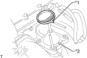
INSTALL CRANKSHAFT POSITION SENSOR
-
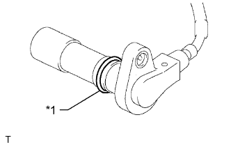
Text in Illustration *1 O-Ring Apply a light coat of engine oil to the O-ring of the crankshaft position sensor.
-
Install the crankshaft position sensor with the bolt.
- Torque:
- 8.5 N*m { 87 kgf*cm, 75 in.*lbf }
Note
Make sure that the O-ring is not cracked or jammed when installing.
-
Connect the crankshaft position sensor connector and attach the wire harness clamp.
-
-
INSTALL CAMSHAFT POSITION SENSOR
-
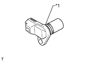
Text in Illustration *1 O-Ring Apply a light coat of engine oil to the O-ring of the camshaft position sensor.
-
Install the camshaft position sensor with the bolt.
- Torque:
- 8.5 N*m { 87 kgf*cm, 75 in.*lbf }
Note
Make sure that the O-ring is not cracked or jammed when installing.
-
Connect the camshaft position sensor connector.
-
-
INSTALL NO. 1 IDLER PULLEY SUB-ASSEMBLY
-
Install the spacer and idler pulley with the bolt.
- Torque:
- 43 N*m { 438 kgf*cm, 32 ft.*lbf }
-
-
INSTALL THERMOSTAT
-
Install a new gasket to the thermostat.
-
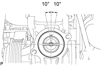
Install the thermostat with the jiggle valve upward.
Tech Tips
The jiggle valve may be set within 10° to either side of the prescribed position.
-
-
INSTALL WATER INLET
-
Install a new gasket and water inlet with the 2 nuts and bolt.
- Torque:
- 28 N*m { 286 kgf*cm, 21 ft.*lbf }
-
-
INSTALL NO. 1 COMPRESSOR MOUNTING BRACKET
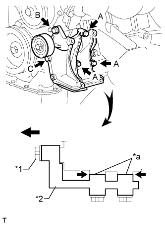
Text in Illustration *1 Bolt B *2 Mounting Bracket *a No Clearance Note
In order to prevent misalignment, which causes belt rattle, the 5 bolts must be tightened exactly as described in the procedures below.
-
Temporarily install the mounting bracket with the 5 bolts.
Tech Tips
Make sure the flanges of the bolts are contacting the bracket surface.
-
Make sure there is no clearance between the cylinder block and bracket as shown in the illustration. Then install the bolt labeled B.
- Torque:
- 45 N*m { 459 kgf*cm, 33 ft.*lbf }
-
Tighten the bolts labeled A and C.
- Torque:
- for bolt A
- 45 N*m { 459 kgf*cm, 33 ft.*lbf }
- for bolt C
- 25 N*m { 250 kgf*cm, 18 ft.*lbf }
-
-
INSTALL GENERATOR ASSEMBLY
-
Install the generator with the 2 bolts.
- Torque:
- 43 N*m { 438 kgf*cm, 32 ft.*lbf }
-
Connect the generator connector.
-
Install the generator wire with the nut.
- Torque:
- 9.8 N*m { 100 kgf*cm, 87 in.*lbf }
-
Install the terminal cap.
-
-
INSTALL INTAKE MANIFOLD
-
Install the intake manifold Click here.
-
-
INSTALL THROTTLE WITH MOTOR BODY ASSEMBLY
-
Text in Illustration *1 Protrusion *2 Groove Install a new gasket to the intake manifold.
Tech Tips
Align the protrusion of the gasket with the groove of the intake manifold.
-
Install the throttle body with motor with the 2 bolts and 2 nuts.
- Torque:
- 9.0 N*m { 92 kgf*cm, 80 in.*lbf }
-
Connect the water by-pass hose.
-
Connect the No. 2 water by-pass hose.
-
Connect the throttle position sensor and throttle control motor connector.
-
-
INSTALL IGNITION COIL ASSEMBLY
-
Install the 4 ignition coils with the 4 bolts.
- Torque:
- 9.0 N*m { 92 kgf*cm, 80 in.*lbf }
-
Connect the 4 ignition coil connectors.
-
-
INSTALL ENGINE ASSEMBLY
-
Install the engine to the vehicle Click here.
-