OIL PUMP REMOVAL

-
REMOVE ENGINE ASSEMBLY
-
Remove the engine from the vehicle Click here.
-
-
REMOVE IGNITION COIL ASSEMBLY
-
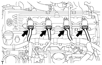
Disconnect the 4 ignition coil connectors.
-
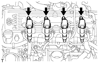
Remove the 4 bolts and 4 ignition coils.
-
-
REMOVE GENERATOR ASSEMBLY
-
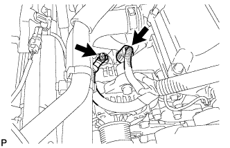
Remove the terminal cap.
-
Remove the nut and generator wire.
-
Disconnect the generator connector.
-
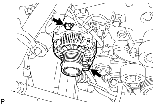
Remove the 2 bolts and generator.
-
-
REMOVE V-RIBBED BELT TENSIONER ASSEMBLY
-
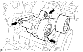
Remove the 3 bolts and belt tensioner.
-
-
REMOVE NO. 1 COMPRESSOR MOUNTING BRACKET
-
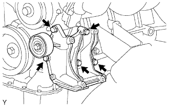
Remove the 5 bolts and compressor mounting bracket.
-
-
REMOVE WATER INLET
-
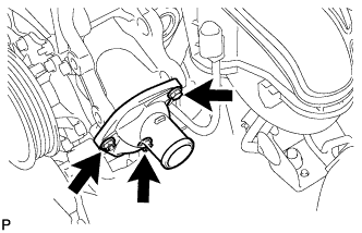
Remove the bolt, 2 nuts, water inlet and gasket.
-
-
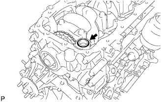
REMOVE THERMOSTAT
-
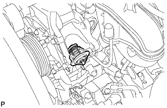
Remove the thermostat from the timing chain cover.
-
-
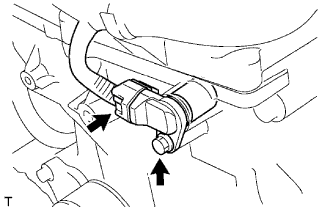
REMOVE THROTTLE WITH MOTOR BODY ASSEMBLY
-
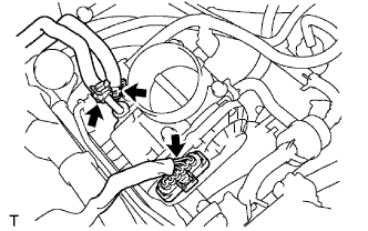
Disconnect the water by-pass hose.
-
Disconnect the No. 2 water by-pass hose.
-
Disconnect the throttle position sensor and throttle control motor connector.
-
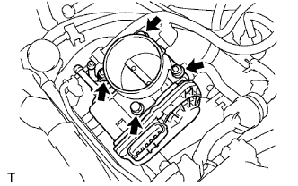
Remove the 2 bolts, 2 nuts and throttle body with motor.
-
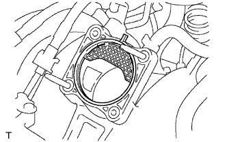
Remove the gasket from the intake manifold.
-
-
REMOVE INTAKE MANIFOLD
-
Remove the intake manifold Click here.
-
-
REMOVE NO. 1 IDLER PULLEY SUB-ASSEMBLY
-
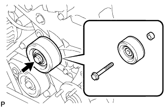
Remove the bolt, idler pulley and spacer.
-
-
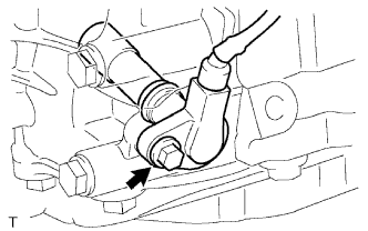
REMOVE CAMSHAFT POSITION SENSOR
-
Disconnect the camshaft position sensor connector.
-
Remove the bolt and camshaft position sensor.
-
-
REMOVE CRANKSHAFT POSITION SENSOR
-
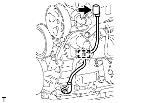
Disconnect the crankshaft position sensor connector and detach the wire harness clamp.
-
Remove the bolt and crankshaft position sensor.
-
-
REMOVE NO. 1 WATER BY-PASS PIPE
-
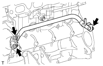
Remove the 2 nuts, bolt, water by-pass pipe and gasket.
-
-
REMOVE CYLINDER HEAD COVER SUB-ASSEMBLY
-
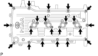
Remove the 19 bolts, 2 nuts, head cover and 2 gaskets.
-
-
REMOVE CRANKSHAFT PULLEY
-
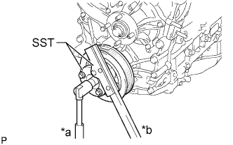
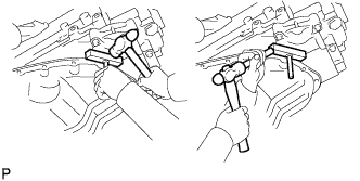
Text in Illustration *a Loosen *b Hold Using SST, hold the crankshaft pulley and loosen the pulley bolt until 2 or 3 threads are screwed into the crankshaft.
- SST
- 09213-54015 ( 91651-60855 )
- 09330-00021
-
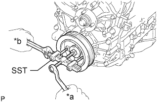
Text in Illustration *a Loosen *b Hold Using SST and the pulley bolt, remove the crankshaft pulley.
- SST
- 09950-50013 ( 09951-05010, 09952-05010, 09953-05010, 09954-05021 )
Tech Tips
Apply lubricant to the threads and end of SST.
-
-
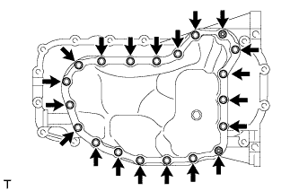
REMOVE NO. 2 OIL PAN SUB-ASSEMBLY
-
Remove the drain plug and gasket.
-
Remove the 18 bolts and 2 nuts.
-
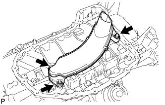
Insert the blade of an oil pan seal cutter between the oil pans. Cut through the applied sealer and remove the oil pan.
Note
Be careful not to damage the contact surfaces of the oil pans.
-
-
REMOVE OIL STRAINER SUB-ASSEMBLY
-
Remove the bolt, 2 nuts, oil strainer and gasket.
-
-
REMOVE OIL PAN SUB-ASSEMBLY
-
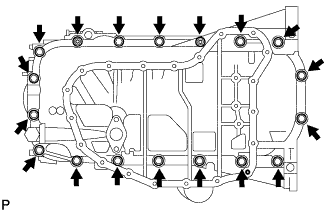
Remove the 16 bolts and 2 nuts.
-
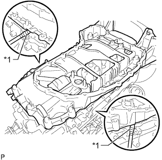
Text in Illustration *1 Protective Tape Remove the oil pan by prying between the oil pan and cylinder block with a screwdriver.
Tech Tips
Tape the screwdriver tip before use.
Note
Be careful not to damage the contact surfaces of the cylinder block and oil pan.
-
Remove the O-ring.
-
-
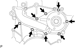
REMOVE TIMING CHAIN COVER SUB-ASSEMBLY
-
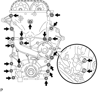
Remove the 19 bolts and 2 nuts shown in the illustration.
-
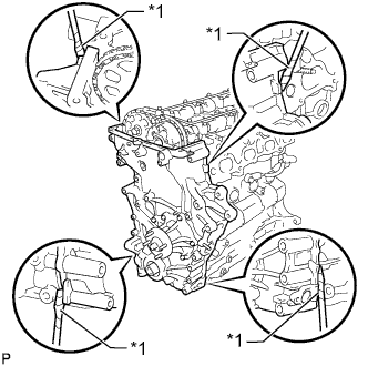
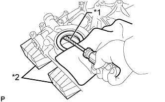
Text in Illustration *1 Protective Tape Remove the timing chain cover by prying between the timing chain cover and cylinder head or cylinder block with a screwdriver.
Tech Tips
Tape the screwdriver tip before use.
Note
Be careful not to damage the contact surfaces of the cylinder head, cylinder block and timing chain cover.
-
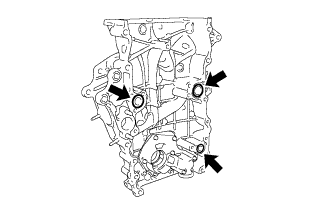
Remove the 3 O-rings.
-
-
REMOVE WATER PUMP ASSEMBLY
-
Remove the 8 bolts, water pump and gasket.
-
-
REMOVE TIMING CHAIN COVER OIL SEAL
-
Text in Illustration *1 Protective Tape *2 Wooden Block Place the timing chain cover on wooden blocks.
-
Using a screwdriver pry out the oil seal.
Tech Tips
Tape the screwdriver tip before use.
-