THERMOSTAT (w/o DPF) INSTALLATION

-
INSTALL THERMOSTAT
-
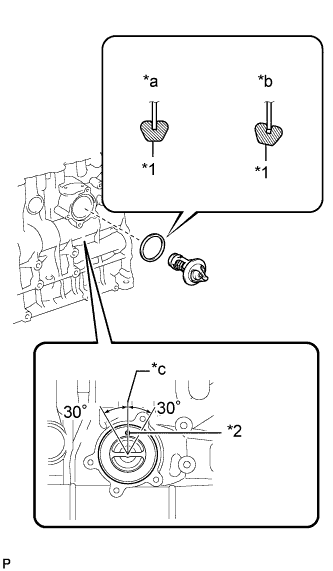
Text in Illustration *1 Gasket *2 Jiggle Valve *a CORRECT *b INCORRECT *c Upward Install a new gasket to the thermostat.
Note
When installing the gasket to the thermostat, be careful not to deform the gasket. Make sure that the gasket is properly installed to the thermostat as shown in the illustration.
-
Install the thermostat to the cylinder block with the jiggle valve facing straight upward.
Tech Tips
The jiggle valve may be set within 30° of either side of the prescribed position.
-
-
INSTALL WATER INLET
-
Install the inlet with the 3 bolts.
- Torque:
- 13 N*m { 133 kgf*cm, 10 ft.*lbf }
-
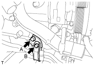
for Automatic Transmission:
Install the hose clamp and bracket with bolt A. Then install the oil pipe clamp with bolt B.
- Torque:
- for bolt A
- 14 N*m { 143 kgf*cm, 10 ft.*lbf }
- for bolt B
- 5.5 N*m { 56 kgf*cm, 49 in.*lbf }
-
-
CONNECT NO. 2 WATER BY-PASS HOSE
-
Connect the No. 2 water by-pass hose to the water inlet.
-
-
CONNECT NO. 2 RADIATOR HOSE
-
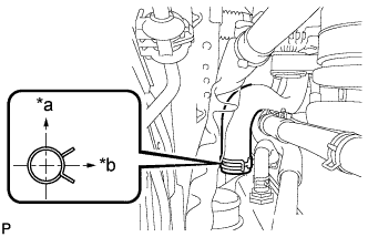
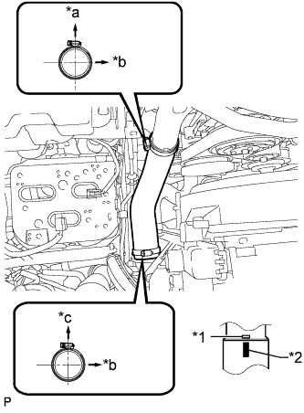
Connect the No. 2 radiator hose.
Tech Tips
Make sure the direction of the hose clamp is as shown in the illustration.
Text in Illustration *a Upper *b RH Side
-
-
INSTALL OIL ENGINE OIL LEVEL DIPSTICK GUIDE
-
Install a new O-ring to the engine oil level dipstick guide.
-
Apply a small amount of clean engine oil to the O-ring.
-
Install the engine oil level dipstick guide with the 2 bolts.
- Torque:
- 8.0 N*m { 82 kgf*cm, 71 in.*lbf }
-
Install the engine oil level dipstick.
-
-
INSTALL VENTILATION PIPE
-
Connect the 2 ventilation hoses and install the ventilation pipe to the cylinder head cover with the bolt.
- Torque:
- 20 N*m { 204 kgf*cm, 15 ft.*lbf }
-
-
INSTALL NO. 1 COMPRESSOR MOUNTING BRACKET
-
Install the No. 1 compressor mounting bracket with the 5 bolts.
- Torque:
- 21 N*m { 214 kgf*cm, 15 ft.*lbf }
-
-
INSTALL GENERATOR ASSEMBLY
-
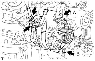
Install the generator with the 2 bolts.
- Torque:
- for bolt A
- 62 N*m { 632 kgf*cm, 46 ft.*lbf }
- for bolt B
- 21 N*m { 214 kgf*cm, 15 ft.*lbf }
-
Install the generator wire with the nut.
- Torque:
- 9.8 N*m { 100 kgf*cm, 87 in.*lbf }
-
Install the terminal cap.
-
Connect the generator connector.
-
-
INSTALL GENERATOR BRACKET
-
Install the generator bracket with the bolts.
- Torque:
- 21 N*m { 214 kgf*cm, 15 ft.*lbf }
-
-
CONNECT COOLER COMPRESSOR ASSEMBLY (w/ Air Conditioning System)
-
Connect the cooler compressor with the 4 bolts.
- Torque:
- 25 N*m { 250 kgf*cm, 18 ft.*lbf }
-
Connect the compressor connector.
-
-
INSTALL NO. 1 VISCOUS HEATER BRACKET SUB-ASSEMBLY (for Cold Area Specification Vehicles)
-
Install the No. 1 viscous heater bracket with the 4 bolts.
- Torque:
- 45 N*m { 459 kgf*cm, 33 ft.*lbf }
-
-
INSTALL VISCOUS WITH MAGNET CLUTCH HEATER ASSEMBLY (for Cold Area Specification Vehicles)
-
Install the viscous heater with magnet clutch with the 2 bolts.
- Torque:
- 45 N*m { 459 kgf*cm, 33 ft.*lbf }
-
Connect the water by-pass hose and water hose.
-
Connect the viscous heater connector.
-
-
INSTALL COMPRESSOR OUTLET ELBOW
-
Install the compressor outlet elbow with the 2 bolts and tighten the hose clamp.
- Torque:
- for bolt
- 20 N*m { 204 kgf*cm, 15 ft.*lbf }
- for hose clamp
- 6.5 N*m { 66 kgf*cm, 58 in.*lbf }
-
Install the wire harness bracket with the bolt.
- Torque:
- 8.0 N*m { 82 kgf*cm, 71 in.*lbf }
-
Attach the 3 wire harness clamps.
-
-
INSTALL NO. 1 AIR HOSE
Note
Before installation, remove any oil residue from the inside of the inlet pipe and intercooler.
-
Text in Illustration *1 Embossed Mark *2 Paint Mark *a Rear Side of Vehicle *b LH Side *c Upper Align the paint mark of the intercooler air hose with the embossed mark of the intercooler.
-
Tighten the 2 clamps.
- Torque:
- 6.5 N*m { 66 kgf*cm, 58 in.*lbf }
-
-
INSTALL AIR CLEANER CASE SUB-ASSEMBLY
-
Install the air cleaner case with the 3 bolts.
- Torque:
- 12 N*m { 122 kgf*cm, 9 ft.*lbf }
-
-
INSTALL AIR CLEANER FILTER ELEMENT SUB-ASSEMBLY
-
INSTALL AIR CLEANER CAP SUB-ASSEMBLY
-
Attach the 4 clamps to install the air cleaner cap.
-
except Cold Area Specification Vehicles:
Attach the 2 clamps and connect the mass air flow meter connector.
-
for Cold Area Specification Vehicles:
Attach the 3 clamps and connect the mass air flow meter connector.
-
-
INSTALL NO. 1 AIR CLEANER HOSE
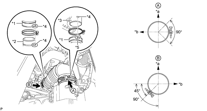
Text in Illustration *1 No. 1 Air Cleaner Hose *2 Compressor Inlet Elbow *3 Air Cleaner Cap *4 Protrusion *5 Groove - - *a Upper Side *b Front Side of Vehicle
-
Install the No. 1 air cleaner hose.
Note
-
When installing the No. 1 air cleaner hose, align its protrusion with the protrusion of the compressor inlet elbow as shown in the illustration.
-
When installing the No. 1 air cleaner hose, align its groove with the protrusion of the air cleaner cap as shown in the illustration.
-
-
Tighten the 2 hose clamps.
- Torque:
- 5.0 N*m { 51 kgf*cm, 44 in.*lbf }
Note
When tightening the 2 hose clamps, make sure that they are positioned as shown in the illustration.
-
-
INSTALL FAN AND GENERATOR V BELT
-
Use the pulley set bolt of the tensioner to rotate the tensioner pulley clockwise, and then install the V belt.
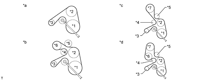
Text in Illustration *1 Crankshaft Pulley *2 Fan Pulley *3 Generator *4 No. 2 Idler Pulley *5 No. 3 Idler Pulley *6 Cooler Compressor *7 Viscous Heater - - *a Type A *b Type C *c Type B *d Type D Note
Make sure that the V belt is set properly on each pulley.
-
Check that the indicator mark of the V-ribbed belt tensioner Click here.
-
-
INSTALL FRONT HEATER BRACKET (for Cold Area Specification Vehicles)
-
Install the front heater bracket with the 2 bolts.
- Torque:
- 25 N*m { 250 kgf*cm, 18 ft.*lbf }
-
-
CONNECT CABLE TO NEGATIVE BATTERY TERMINAL
Note
When disconnecting the cable, some systems need to be initialized after the cable is reconnected Click here.
-
ADD ENGINE COOLANT
-
Tighten the radiator drain cock plug by hand.
-
Tighten the cylinder block drain cock plug.
- Torque:
- 8.0 N*m { 82 kgf*cm, 71 in.*lbf }
-
Fill the radiator with TOYOTA Super Long Life Coolant (SLLC) to the B line of the reservoir tank.
Standard Capacity Item Specified Condition for Automatic Transmission w/ Rear Heater 14.9 liters (15.7 US qts, 13.1 Imp. qts) w/o Rear Heater 13.1 liters (13.8 US qts, 11.5 Imp. qts) for Manual Transmission w/ Rear Heater 15.0 liters (15.8 US qts, 13.2 Imp. qts) w/o Rear Heater 13.2 liters (13.9 US qts, 11.6 Imp. qts) Tech Tips
-
TOYOTA vehicles are filled with TOYOTA SLLC at the factory. In order to avoid damage to the engine cooling system and other technical problems, only use TOYOTA SLLC or similar high quality ethylene glycol based non-silicate, non-amine, non-nitrite, non-borate coolant with long-life hybrid organic acid technology (coolant with long-life hybrid organic acid technology consists of a combination of low phosphates and organic acids).
-
Please contact your TOYOTA dealer for further details.
-
for Cold Area Specification Vehicles:
Please contact any authorized TOYOTA dealer or repairer or another duly qualified and equipped professional for further details.
Note
Never use water as a substitute for engine coolant.
-
-
Press the inlet and outlet radiator hoses several times by hand, and then check the level of the coolant.
If the coolant level drops below the B line, add TOYOTA SLLC to the B line.
-
Install the radiator reservoir cap.
-
Using a wrench, install the vent plug.
- Torque:
- 2.0 N*m { 20 kgf*cm, 18 in.*lbf }
-
Bleed air from the cooling system.
-
Warm up the engine until the thermostat opens. While the thermostat is open, circulate the coolant for several minutes.
-
Maintain the engine speed at 2500 to 3000 rpm.
-
Press the inlet and outlet radiator hoses several times by hand to bleed air.
CAUTION:
When pressing the radiator hoses:
-
Wear protective gloves.
-
Be careful as the radiator hoses are hot.
-
Keep your hands away from the radiator fan.
-
-
Stop the engine and wait until the coolant cools down to ambient temperature.
CAUTION:
Do not remove the radiator reservoir cap while the engine and radiator are still hot. Pressurized, hot engine coolant and steam may be released and cause serious burns.
-
-
After the coolant cools down, check that the coolant level is at the FULL line.
If the coolant level is below the FULL line, add TOYOTA SLLC to the FULL line.
-
-
INSPECT FOR ENGINE COOLANT LEAK
Note
Before each inspection, turn the A/C switch off.
CAUTION:
Do not remove the radiator reservoir cap while the engine and radiator are still hot. Pressurized, hot engine coolant and steam may be released and cause serious burns.
-
Fill the radiator with coolant and attach a radiator cap tester.
-
Warm up the engine.
-
Using the radiator cap tester, increase the pressure inside the radiator to 123 kPa (1.3 kgf/cm2, 18 psi), and check that the pressure does not drop.
If the pressure drops, check the hoses, radiator and water pump for leaks. If no external leaks are found, check the heater core, cylinder block and head.
-
-
INSTALL FRONT NO. 1 FENDER APRON TO FRAME SEAL RH
-
Install the front No. 1 fender apron to frame seal RH with the 5 clips.
-
-
INSTALL FRONT FENDER APRON SEAL RH
-
Install the front fender apron seal RH with the 4 clips.
-
-
INSTALL NO. 1 ENGINE UNDER COVER SUB-ASSEMBLY
-
Install the No. 1 engine under cover with the 4 bolts.
- Torque:
- 29 N*m { 296 kgf*cm, 21 ft.*lbf }
-
-
INSTALL FRONT BUMPER LOWER COVER
-
Install the lower front bumper cover with the clip and 5 bolts.
- Torque:
- 8.0 N*m { 82 kgf*cm, 71 in.*lbf }
-
-
INSTALL UPPER RADIATOR SUPPORT SEAL
-
Install the upper radiator support seal with the 13 clips.
-