EXHAUST PIPE (w/ DPF) INSTALLATION

-
INSTALL CONVERTER PROTECTOR STAY
-
Install the 2 No. 1 converter protector stays and 2 No. 2 converter protector stays to the front exhaust pipe.
-
-
INSTALL MONOLITHIC CONVERTER PROTECTOR
-
Install the upper monolithic converter protector and lower monolithic converter protector with the 4 bolts and 4 nuts.
- Torque:
- 11 N*m { 107 kgf*cm, 8 ft.*lbf }
-
-
INSTALL EXHAUST PIPE CLAMP SUB-ASSEMBLY
-
Install the exhaust pipe clamp with the bolt.
- Torque:
- 11 N*m { 107 kgf*cm, 8 ft.*lbf }
-
-
INSTALL NO. 3 WIRING HARNESS CLAMP BRACKET
-
Install the No. 3 wiring harness clamp bracket with the bolt.
- Torque:
- 18 N*m { 184 kgf*cm, 13 ft.*lbf }
-
-
INSTALL NO. 3 EXHAUST GAS TEMPERATURE SENSOR
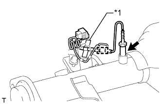
Text in Illustration *1 Blue Tape Note
If the sensor is dropped, replace it with a new one.
-
Using a 14 mm union nut wrench, install the No. 3 exhaust gas temperature sensor.
- Torque:
- 30 N*m { 306 kgf*cm, 22 ft.*lbf }
Note
Use the formula to calculate special torque values for situations where a union nut wrench is combined with a torque wrench Click here.
Tech Tips
The identification tape on the exhaust gas temperature sensor is blue.
-
Attach the No. 3 exhaust gas temperature sensor wire harness.
-
-
INSTALL NO. 2 EXHAUST GAS TEMPERATURE SENSOR
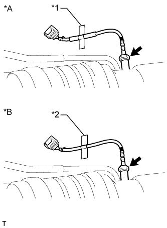
Text in Illustration *A for Automatic Transmission *B for Manual Transmission *1 Yellow Tape *2 Red Tape Note
If the sensor is dropped, replace it with a new one.
-
Using a 14 mm union nut wrench, install the No. 2 exhaust gas temperature sensor.
- Torque:
- 30 N*m { 306 kgf*cm, 22 ft.*lbf }
Note
Use the formula to calculate special torque values for situations where a union nut wrench is combined with a torque wrench Click here.
Tech Tips
Refer to the illustration to identify the No. 2 exhaust gas temperature sensor being used.
-
-
INSTALL EXHAUST GAS TEMPERATURE SENSOR
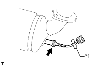
Text in Illustration *1 Green Tape Note
If the sensor is dropped, replace it with a new one.
-
Using a 14 mm union nut wrench, install the exhaust gas temperature sensor.
- Torque:
- 30 N*m { 306 kgf*cm, 22 ft.*lbf }
Note
Use the formula to calculate special torque values for situations where a union nut wrench is combined with a torque wrench Click here.
Tech Tips
The identification tape on the exhaust gas temperature sensor is green.
-
-
INSTALL FRONT EXHAUST PIPE ASSEMBLY
-
Install a new gasket and the front exhaust pipe to the No. 2 turbine outlet elbow with 3 new nuts.
- Torque:
- 54 N*m { 554 kgf*cm, 40 ft.*lbf }
-
Connect the front exhaust pipe to the 2 exhaust pipe supports.
Tech Tips
Install the exhaust pipe supports after installing the No. 3 frame crossmember.
-
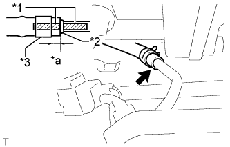
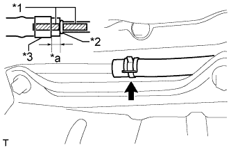
Text in Illustration *1 Paint Mark *2 Stopper *3 Clip *a 4 to 10 mm (0.157 to 0.394 in.) Connect the No. 7 exhaust pipe air hose to the front exhaust pipe with a new clip.
Note
-
Align the paint marks of the front exhaust pipe and No. 7 exhaust pipe air hose and insert the No. 7 exhaust pipe air hose until it contacts the stopper.
-
Make sure the clip is 4 to 10 mm (0.157 to 0.394 in.) from the end of the No. 7 exhaust pipe air hose when installing the clip.
-
Make sure that there is no slack in the No. 7 exhaust pipe air hose, and that it is not twisted or bent.
-
Take care not to damage the inner or outer surface of the No. 7 exhaust pipe air hose when installing it. If the No. 7 exhaust pipe air hose is damaged, replace it with a new one.
-
-
Text in Illustration *1 Paint Mark *2 Stopper *3 Clip *a 4 to 10 mm (0.157 to 0.394 in.) Connect the No. 6 exhaust pipe air hose to the front exhaust pipe with a new clip.
Note
-
Align the paint marks of the front exhaust pipe and No. 6 exhaust pipe air hose and insert the No. 6 exhaust pipe air hose until it contacts the stopper.
-
Make sure the clip is 4 to 10 mm (0.157 to 0.394 in.) from the end of the exhaust pipe air hose when installing the clip.
-
Make sure that there is no slack in the No. 6 exhaust pipe air hose, and that it is not twisted or bent.
-
Take care not to damage the inner or outer surface of the No. 6 exhaust pipe air hose when installing it. If the No. 6 exhaust pipe air hose is damaged, replace it with a new one.
-
-
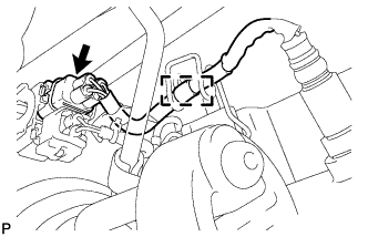
Connect the No. 3 exhaust gas temperature sensor connector.
-
Connect the No. 2 exhaust gas temperature sensor connector.
-
Connect the exhaust gas temperature sensor connector.
-
-
INSTALL AIR FUEL RATIO SENSOR
-
Disconnect the air fuel ratio sensor connector and detach the clamp.
-

Using SST, remove the air fuel ratio sensor from the front exhaust pipe.
- SST
- 09224-00010
-
-
INSTALL NO. 3 EXHAUST PIPE SUPPORT BRACKET
-
Install the No. 3 exhaust pipe support bracket with the 2 bolts.
- Torque:
- 19 N*m { 194 kgf*cm, 14 ft.*lbf }
-
-
INSTALL NO. 2 EXHAUST PIPE SUPPORT BRACKET
-
Install the No. 2 exhaust pipe support bracket with the 2 bolts.
- Torque:
- 19 N*m { 194 kgf*cm, 14 ft.*lbf }
-
-
INSTALL NO. 3 FRAME CROSSMEMBER SUB-ASSEMBLY (for Manual Transmission)
-
Install the No. 3 frame crossmember sub-assembly with the 4 bolts and 4 nuts.
- Torque:
- 72 N*m { 734 kgf*cm, 53 ft.*lbf }
-
Install the 4 bolts to the No. 3 frame crossmember sub-assembly.
- Torque:
- 30 N*m { 306 kgf*cm, 22 ft.*lbf }
-
-
INSTALL NO. 3 FRAME CROSSMEMBER SUB-ASSEMBLY (for Automatic Transmission)
-
Install the frame crossmember to the rear engine mounting insulator with the 4 bolts.
- Torque:
- 30 N*m { 306 kgf*cm, 22 ft.*lbf }
-
Install the frame crossmember with the 4 bolts and 4 nuts.
- Torque:
- 72 N*m { 734 kgf*cm, 53 ft.*lbf }
-
-
INSTALL FRONT SUSPENSION MEMBER BRACKET LH AND RH (for Automatic Transmission)
-
Install the front suspension member bracket LH and front suspension member bracket RH with the 8 bolts.
- Torque:
- 33 N*m { 337 kgf*cm, 24 ft.*lbf }
-
-
INSTALL FRONT SUSPENSION MEMBER BRACKET RH (for Manual Transmission)
-
Install the front suspension member bracket RH with the 4 bolts.
- Torque:
- 33 N*m { 337 kgf*cm, 24 ft.*lbf }
-
-
INSTALL FRONT SUSPENSION MEMBER BRACKET LH (for Manual Transmission)
-
Install the front suspension member bracket LH with the 4 bolts.
- Torque:
- 33 N*m { 337 kgf*cm, 24 ft.*lbf }
-
-
INSTALL CENTER EXHAUST PIPE ASSEMBLY
-
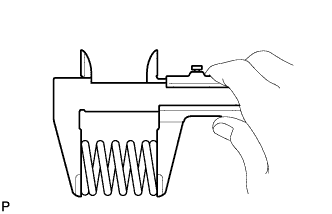
Using a vernier caliper, measure the free length of the compression spring.
Minimum free length 43 mm (1.693 in.)
-
If the free length is less than the minimum, replace the compression spring.
-
-
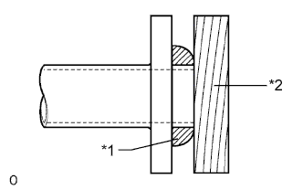
Text in Illustration *1 Gasket *2 Wooden Block Using a plastic-faced hammer and wooden block, tap in a new gasket until its surface is flush with the front exhaust pipe.
Note
-
Be sure to install the gasket so that it faces the correct direction.
-
Do not reuse the gasket.
-
Do not damage the gasket.
-
When connecting the exhaust pipe, do not push in the gasket with the exhaust pipe.
-
-
for 3 Door:
Connect the center exhaust pipe to the 2 exhaust pipe supports.
-
for 5 Door:
-
Install the No. 1 exhaust pipe heat insulator with the nut.
- Torque:
- 8.5 N*m { 87 kgf*cm, 75 in.*lbf }
-
Install the exhaust pipe damper with the 2 bolts.
- Torque:
- 19 N*m { 194 kgf*cm, 14 ft.*lbf }
-
Connect the center exhaust pipe to the 3 exhaust pipe supports.
-
-
Install the center exhaust pipe and 2 compression springs with the 2 bolts.
- Torque:
- 43 N*m { 438 kgf*cm, 32 ft.*lbf }
-
-
INSTALL TAILPIPE ASSEMBLY
-
Connect the tailpipe to the exhaust pipe support.
-
Install a new gasket to the center exhaust pipe.
-
Connect the tailpipe to the center exhaust pipe.
-
Install the 2 bolts.
- Torque:
- 48 N*m { 489 kgf*cm, 35 ft.*lbf }
-
-
INSPECT FOR EXHAUST GAS LEAK
-
If gas is leaking, tighten the areas necessary to stop the leak. Replace damaged parts as necessary.
-