EXHAUST PIPE INSTALLATION

-
INSTALL HEATED OXYGEN SENSOR (for Bank 1 Sensor 2)
-
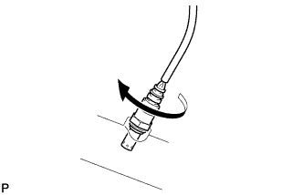
Temporarily install the sensor to the exhaust pipe by hand.
-
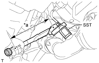
Text in Illustration *a Fulcrum Length Using SST, tighten the sensor.
- SST
- 09224-00010
- Torque:
- without SST
- 44 N*m { 449 kgf*cm, 32 ft.*lbf }
- with SST
- 40 N*m { 408 kgf*cm, 30 ft.*lbf }
Tech Tips
-
Use a torque wrench with a fulcrum length of 30 cm (11.8 in.). When using a torque wrench with a fulcrum length that is not 30 cm (11.8 in.), calculate the torque specification for the torque wrench and SST based on the "without SST" torque specification Click here.
-
Make sure SST and the wrench are connected in a straight line.
-
Connect the sensor connector.
-
-
INSTALL HEATED OXYGEN SENSOR (for Bank 2 Sensor 2)
-
Temporarily install the sensor to the exhaust pipe by hand.
-
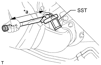
Text in Illustration *a Fulcrum Length Using SST, tighten the sensor.
- SST
- 09224-00010
- Torque:
- without SST
- 44 N*m { 449 kgf*cm, 32 ft.*lbf }
- with SST
- 40 N*m { 408 kgf*cm, 30 ft.*lbf }
Tech Tips
-
Use a torque wrench with a fulcrum length of 30 cm (11.8 in.). When using a torque wrench with a fulcrum length that is not 30 cm (11.8 in.), calculate the torque specification for the torque wrench and SST based on the "without SST" torque specification Click here.
-
Make sure SST and the wrench are connected in a straight line.
-
-
INSTALL FRONT NO. 2 EXHAUST PIPE ASSEMBLY
-
Install a new gasket and the No. 2 front exhaust pipe to the exhaust manifold with 2 new nuts.
- Torque:
- 54 N*m { 554 kgf*cm, 40 ft.*lbf }
-
Connect the heated oxygen sensor connector.
-
-
INSTALL EXHAUST PIPE STOPPER BRACKET
-
Install the stopper bracket with the 2 bolts.
- Torque:
- 19 N*m { 194 kgf*cm, 14 ft.*lbf }
-
-
INSTALL FRONT EXHAUST PIPE ASSEMBLY
-
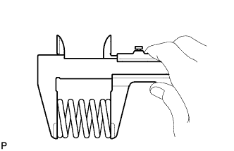
Using a vernier caliper, measure the free length of the compression spring.
Minimum free length 43 mm (1.693 in.)
-
If the free length is less than the minimum, replace the compression spring.
-
-
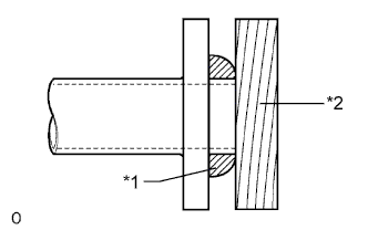
Text in Illustration *1 Gasket *2 Wooden Block Using a plastic-faced hammer and wooden block, tap in a new gasket until its surface is flush with the front exhaust pipe.
Note
-
Be sure to install the gasket so that it faces the correct direction.
-
Do not reuse the gasket.
-
Do not damage the gasket.
-
When connecting the exhaust pipe, do not push in the gasket with the exhaust pipe.
-
-
Install a new gasket and the front exhaust pipe to the exhaust manifold with 2 new nuts.
- Torque:
- 54 N*m { 554 kgf*cm, 40 ft.*lbf }
-
Connect the front exhaust pipe to the front No. 2 exhaust pipe with the 2 bolts.
- Torque:
- 48 N*m { 489 kgf*cm, 35 ft.*lbf }
-
Connect the heated oxygen sensor connector.
-
-
INSTALL CENTER EXHAUST PIPE ASSEMBLY
-
Connect the center exhaust pipe to the 3 exhaust pipe supports.
-
Install the center exhaust pipe with the 2 compression springs and 4 bolts.
- Torque:
- 43 N*m { 438 kgf*cm, 32 ft.*lbf }
-
-
INSTALL TAILPIPE ASSEMBLY
-
Install the tailpipe to the exhaust pipe support.
-
Install a new gasket to the center exhaust pipe.
-
Install the 2 bolts.
- Torque:
- 48 N*m { 489 kgf*cm, 35 ft.*lbf }
-
-
INSPECT FOR EXHAUST GAS LEAK
-
If gas is leaking, tighten the areas necessary to stop the leak. Replace damaged parts as necessary.
-