EXHAUST MANIFOLD REMOVAL

-
REMOVE UPPER RADIATOR SUPPORT SEAL
-
Remove the 13 clips and upper radiator support seal.
-
-
REMOVE V-BANK COVER
-
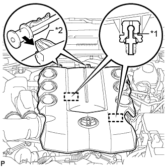
Text in Illustration *1 Pin *2 Hook Raise the front of the V-bank cover to detach the 2 pins. Then remove the 2 V-bank cover hooks from the bracket, and remove the V-bank cover.
-
-
REMOVE AIR CLEANER CAP AND HOSE
-
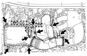
Remove the air cleaner cap and hose.
-
Disconnect the mass air flow meter connector, vacuum hose and ventilation hose and detach the 4 clamps.
-
Loosen the clamp.
-
Unfasten the 4 hook clamps, and then remove the bolt and air cleaner cap and hose.
-
-
-
REMOVE AIR CLEANER CASE SUB-ASSEMBLY
-
Remove the air cleaner filter element.
-
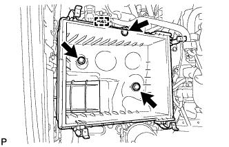
Detach the wire harness clamp.
-
Remove the 3 bolts and air cleaner case.
-
-
REMOVE FRONT FENDER APRON SEAL LH
-
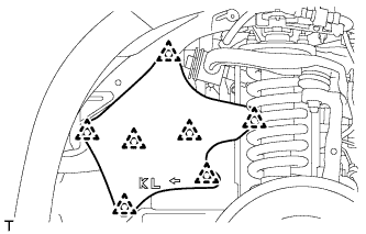
w/ KDSS:
Remove the 7 clips and fender apron seal.
-
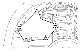
w/o KDSS:
Remove the 5 clips and fender apron seal.
-
-
REMOVE FRONT FENDER APRON SEAL RH
-
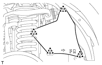
Remove the 4 clips and fender apron seal.
-
-
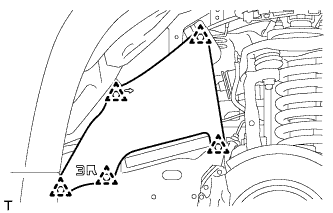
REMOVE FRONT NO. 1 FENDER APRON TO FRAME SEAL LH
-
Remove the 5 clips and frame seal.
-
-
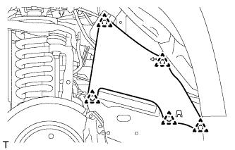
REMOVE FRONT NO. 1 FENDER APRON TO FRAME SEAL RH
-
Remove the 5 clips and fender apron seal.
-
-
REMOVE FRONT EXHAUST PIPE ASSEMBLY
-
Remove the front exhaust pipe Click here.
-
-
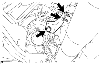
REMOVE MANIFOLD STAY
-
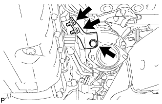
Remove the 3 bolts and manifold stay.
-
-
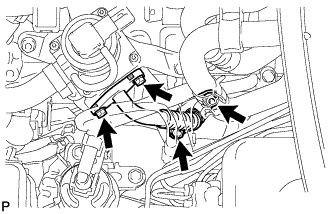
REMOVE AIR TUBE (w/ Secondary Air Injection System)
-
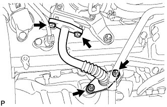
Remove the 2 bolts, 2 nuts and air tube.
-
Remove the 2 gaskets from the air tube.
Note
Be careful not to damage the installation surface of the gaskets.
-
-
DISCONNECT NO. 2 STEERING INTERMEDIATE SHAFT SUB-ASSEMBLY (for RHD)
-
for Manual Tilt and Manual Telescopic Steering Column:
Disconnect the No. 2 steering intermediate shaft Click here.
-
for Power Tilt and Power Telescopic Steering Column:
Disconnect the No. 2 steering intermediate shaft Click here.
-
-
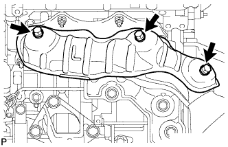
REMOVE NO. 1 EXHAUST MANIFOLD HEAT INSULATOR
-
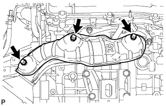
Remove the 3 bolts and heat insulator.
-
-
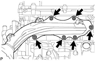
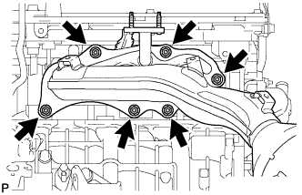
REMOVE EXHAUST MANIFOLD SUB-ASSEMBLY RH
-

w/ Secondary Air Injection System:
-
Disconnect the air fuel ratio sensor connector.
-
Remove the 6 nuts, manifold and gasket.
-
-
w/o Secondary Air Injection System:
-
Disconnect the air fuel ratio sensor connector.
-
Remove the 6 nuts, manifold and gasket.
-
-
-
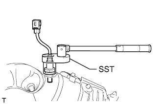
REMOVE AIR FUEL RATIO SENSOR (for Bank 1 Sensor 1)
-
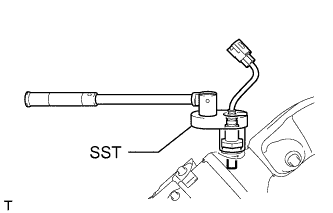
Using SST, remove the sensor.
- SST
- 09224-00010
-
-
REMOVE NO. 2 MANIFOLD STAY
-
Remove the 3 bolts and No. 2 manifold stay.
-
-
REMOVE NO. 2 AIR TUBE (w/ Secondary Air Injection System)
-
Remove the 2 bolts, 2 nuts and No. 2 air tube.
-
Remove the 2 gaskets from the No. 2 air tube.
Note
Be careful not to damage the installation surface of the gaskets.
-
-
REMOVE NO. 2 EXHAUST MANIFOLD HEAT INSULATOR
-
Remove the 3 bolts and heat insulator.
-
-
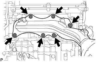
REMOVE EXHAUST MANIFOLD SUB-ASSEMBLY LH
-
w/ Secondary Air Injection System:
-
Disconnect the air fuel ratio sensor connector.
-
Remove the 6 nuts, manifold and gasket.
-
-
w/o Secondary Air Injection System:
-
Disconnect the air fuel ratio sensor connector.
-
Remove the 6 nuts, manifold and gasket.
-
-
-
REMOVE AIR FUEL RATIO SENSOR (for Bank 2 Sensor 1)
-
Using SST, remove the sensor.
- SST
- 09224-00010
-