AIR SWITCHING VALVE REMOVAL

-
REMOVE AIR CLEANER AND HOSE
-
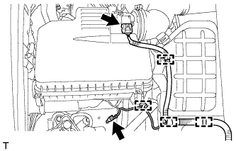
Detach the 3 clamps and disconnect the mass air flow meter connector.
-
Remove the bolt, detach the clamp and disconnect the ground wire.
-
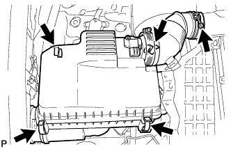
Detach the 4 clamps.
-
Loosen the hose clamp and remove the air cleaner cap.
-
-
REMOVE AIR CLEANER CASE
-
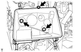
Remove the air cleaner filter element.
-
Remove the 3 bolts and air cleaner case.
-
-
REMOVE FRONT NO. 1 FENDER APRON TO FRAME SEAL RH
-
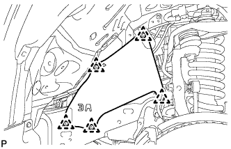
Remove the 5 clips and front No. 1 fender apron to frame seal.
-
-
DISCONNECT NO. 1 AIR INJECTION SYSTEM HOSE
-
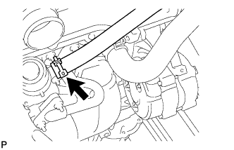
Disconnect the No. 1 air injection system hose.
-
-
REMOVE NO. 1 EXHAUST MANIFOLD HEAT INSULATOR
-
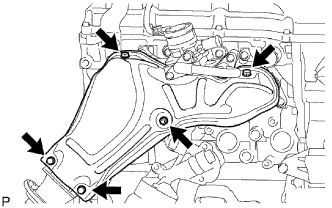
Remove the 5 bolts and No. 1 exhaust manifold heat insulator.
Tech Tips
-
It is only necessary to move the No. 1 exhaust manifold heat insulator so that the intake pipe can be removed in a later step.
-
It is not possible to fully remove the No. 1 exhaust manifold heat insulator in this step.
-
-
-
REMOVE NO. 4 INTAKE PIPE
-
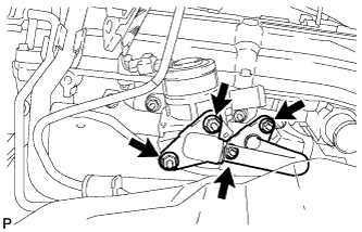
Remove the 4 nuts, No. 4 intake pipe and 2 gaskets.
Note
Be careful not to damage the installation surface of the gaskets.
-
-
REMOVE AIR SWITCHING VALVE ASSEMBLY
-
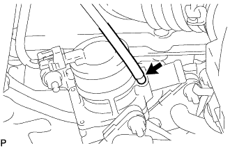
w/ Manifold Absolute Pressure Sensor:
Disconnect the vacuum hose.
-
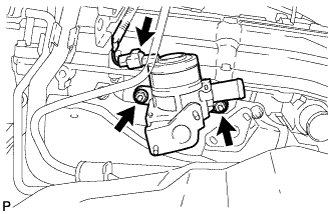
Disconnect the connector.
-
Remove the 2 nuts and air switching valve.
-
Remove the No. 1 exhaust manifold heat insulator.
-