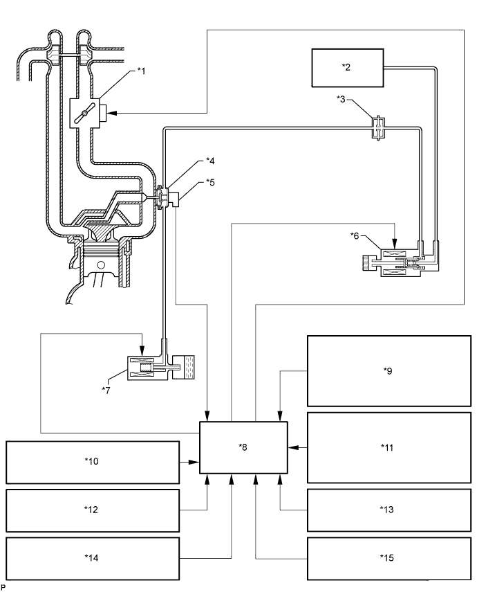
| *1 |
Diesel Throttle Body |
*2 |
Vacuum Pump |
| *3 |
Vacuum Switching Valve (for EGR Bypass Valve) |
*4 |
EGR Bypass Valve |
| *5 |
EGR Cooler |
*6 |
Electric EGR Control Valve |
| *7 |
Vacuum Damper |
*8 |
EGR Valve Position Sensor |
| *9 |
Electric Vacuum Regulating Valve (for EGR) |
*10 |
Vacuum Switching Valve (for EGR Cut) |
| *11 |
ECM |
*12 |
Engine Coolant Temperature Sensor |
| *13 |
Atmospheric Pressure |
*14 |
Manifold Absolute Pressure Sensor |
| *15 |
Accelerator Pedal Position Sensor |
*16 |
Mass Air Flow Meter |
| *17 |
Intake Air Temperature Sensor |
*18 |
Crankshaft Position Sensor |