FRONT DOOR WINDOW FRAME MOULDING REMOVAL

-
PRECAUTION
Note
After turning the ignition switch off, waiting time may be required before disconnecting the cable from the negative (-) battery terminal. Therefore, make sure to read the disconnecting the cable from the negative (-) battery terminal notices before proceeding with work Click here.
-
DISCONNECT CABLE FROM NEGATIVE BATTERY TERMINAL
CAUTION:
Wait at least 90 seconds after disconnecting the cable from the negative (-) battery terminal to disable the SRS system.
Note
When disconnecting the cable, some systems need to be initialized after the cable is reconnected Click here.
-
REMOVE OUTER REAR VIEW MIRROR ASSEMBLY
-
REMOVE DOOR SIDE AIRBAG SENSOR
-
Check that the ignition switch is off.
-
Check that the cable is disconnected from the negative (-) battery terminal.
CAUTION:
Wait at least 90 seconds after disconnecting the cable from the negative (-) battery terminal to disable the SRS system.
-
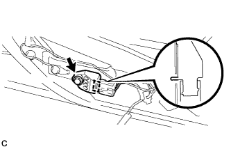
Disconnect the connector from the door side airbag sensor.
Note
When disconnecting any airbag connector, take care not to damage the airbag wire harness.
-
Push down the white housing lock and slide the yellow CPA. (At this time, the connector cannot be disconnected yet.)
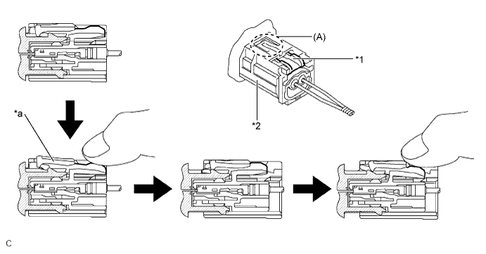
Text in Illustration *1 White Housing Lock *2 Yellow CPA *a Connector Lock is Released - - -
Push down the white housing lock again and disconnect the connector.
Note
Do not push down the part (A) shown in the illustration when disconnecting.
-
-
Remove the bolt and door side airbag sensor from the front door panel.
Note
Loosen the bolt while holding the door side airbag sensor because the door side airbag sensor pin (stopper) is easily damaged.
-
After disconnecting the connector, check that the position of the white housing lock is correct as shown in the illustration.
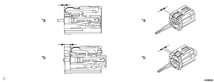
Text in Illustration *a Incorrect *b Correct
-
-
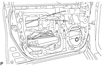
REMOVE FRONT DOOR SERVICE HOLE COVER
-
Remove the bolt.
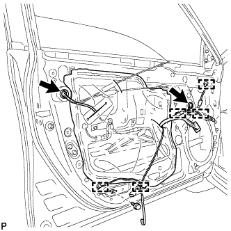
-
Disconnect each connector.
-
Disengage the 5 clamps.
-
Remove the front door service hole cover.
Tech Tips
Remove any remaining butyl tape from the door.
-
-
REMOVE FRONT DOOR GLASS SUB-ASSEMBLY
-
Remove the grommet.
-
Connect the cable to the negative (-) battery terminal.
-
Connect the power window regulator master switch assembly and move the front door glass sub-assembly so that the door glass bolts can be seen.
-
Disconnect the cable from the negative (-) battery terminal.
CAUTION:
Wait at least 90 seconds after disconnecting the cable from the negative (-) battery terminal to disable the SRS system.
Note
When disconnecting the cable, some systems need to be initialized after the cable is reconnected Click here.
-
Disconnect the power window regulator master switch assembly.
-
Remove the 2 bolts.
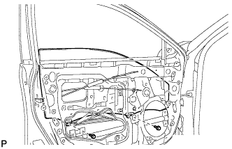
Note
After the bolts are removed, do not allow the door glass to fall.
-
Remove the front door glass sub-assembly as indicated by the arrows, in the order shown in the illustration.
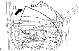
Note
Do not damage the door glass.
-
-
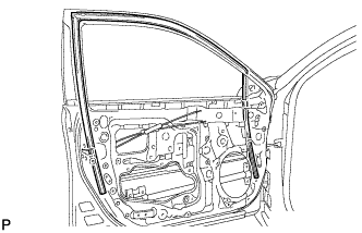
REMOVE FRONT DOOR GLASS RUN
-
Remove the front door glass run.
-
-
REMOVE FRONT DOOR BELT MOULDING ASSEMBLY
-
Put protective tape around the front door belt moulding assembly.
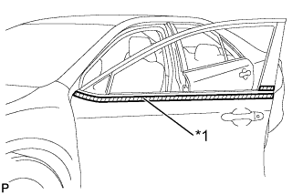
Text in Illustration *1 Protective Tape -
Using a screwdriver with the tip wrapped with protective tape, disengage the 6 claws and remove the front door belt moulding assembly.
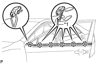
Text in Illustration *1 Protective Tape Tech Tips
Tape the screwdriver tip before use.
-
-
REMOVE FRONT DOOR CHECK ASSEMBLY
-
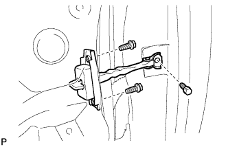
Remove the 3 bolts and front door check assembly.
-
-
REMOVE FRONT DOOR WEATHERSTRIP
-
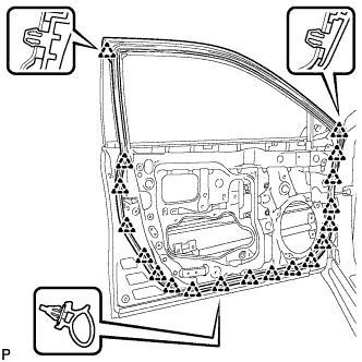
Using a clip remover, disengage the 19 clips and remove the front door weatherstrip.
-
-
REMOVE FRONT DOOR REAR WINDOW FRAME MOULDING
Tech Tips
When removing the front door rear window frame moulding, heat the vehicle body and front door rear window frame moulding using a heat light.
Heating Temperature Item Temperature Vehicle Body 40 to 60°C (104 to 140°F) Moulding 20 to 30°C (68 to 86°F) Note
Do not heat the vehicle body or moulding excessively.
-
Using a heat light, heat the front door rear window frame moulding.
-
Using a moulding remover, disengage the clip and remove the front door rear window frame moulding.
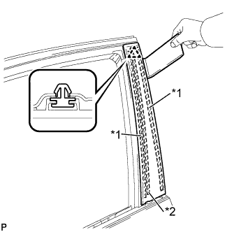
Text in Illustration *1 Double-sided Tape *2 Caulking Sponge
-
-
REMOVE FRONT DOOR UPPER WINDOW FRAME MOULDING
-
Insert a 4.0 mm (0.157 in.) drill bit into a drill.
-
Tape a 4.0 mm (0.157 in.) drill bit 5.0 mm (0.197 in.) from the tip as shown in the illustration.
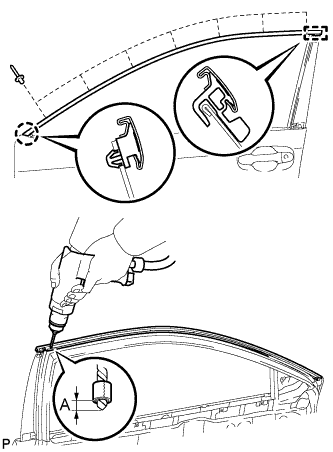
Area Dimension A 5.0 mm Note
Tape the 4.0 mm (0.157 in.) drill bit to prevent the drill bit from going too deep.
-
Lightly press the drill against the rivets to drill off the rivet flanges, and remove the 7 rivets.
Note
-
Pressing the drill too firmly will cause the rivet to turn and result in the rivet not being drilled through.
-
Prying the rivets with the drill may damage the rivet installation holes or drill bit.
-
Be careful of the drilled rivets, as they may be hot.
-
-
Using a vacuum cleaner, remove the rivet fragments and shavings from the drilled areas.
-
Disengage the claw and guide, and remove the front door upper window frame moulding from the door frame.
-