FRONT DOOR WINDOW FRAME MOULDING INSTALLATION

-
PRECAUTION
Note
After turning the ignition switch off, waiting time may be required before disconnecting the cable from the negative (-) battery terminal. Therefore, make sure to read the disconnecting the cable from the negative (-) battery terminal notices before proceeding with work Click here.
-
INSTALL FRONT DOOR UPPER WINDOW FRAME MOULDING
-
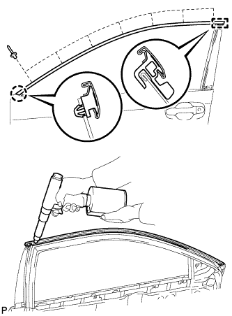
Engage the claw and guide of the front door upper window frame moulding to the door frame.
-
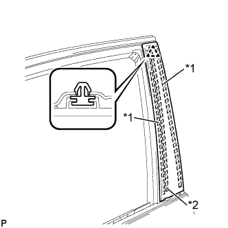
Using an air riveter or hand riveter with a nose piece, install the front door upper window frame moulding with 7 new rivets.
Tech Tips
If the mandrel of the rivet does not come off on the first operation of the rivet gun, slide the rivet gun forward on the mandrel and operate it again.
Note
-
Do not pry the rivet with the riveter, as this will cause damage to the riveter and mandrel.
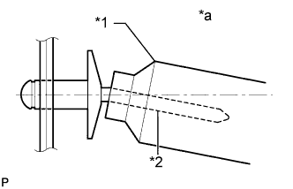
Text in Illustration *1 Riveter *2 Mandrel *a Incorrect -
Confirm that the rivets are seated properly against the moulding. Do not tilt the riveter when installing the rivet to the moulding. Do not leave any space between the rivet head and moulding.
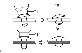
Text in Illustration *1 Riveter *a Incorrect -
Do not leave any space between the moulding and door frame. Firmly hold the 2 items together while installing the rivet.
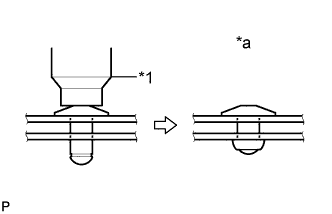
Text in Illustration *1 Riveter *a Incorrect
-
-
-
INSTALL FRONT DOOR REAR WINDOW FRAME MOULDING
Tech Tips
When installing a new front door rear window frame moulding, heat the vehicle body and front door rear window frame moulding using a heat light.
Heating Temperature Item Temperature Vehicle Body 40 to 60°C (104 to 140°F) Moulding 20 to 30°C (68 to 86°F) Note
Do not heat the vehicle body or front door rear window frame moulding excessively.
-
Clean the vehicle body surface.
-
Using a heat light, heat the vehicle body surface.
-
Remove the double-sided tape from the vehicle body.
-
Wipe off any tape adhesive residue with cleaner.
-
-
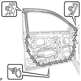
Install a new front door rear window frame moulding.
Text in Illustration *1 Double-sided Tape *2 Caulking Sponge -
Using a heat light, heat the vehicle body and front door rear window frame moulding.
-
Remove the release paper from the face of the front door rear window frame moulding.
Tech Tips
After removing the release paper, keep the exposed adhesive free from foreign matter.
-
Install the front door rear window frame moulding with the clip.
-
-
-
INSTALL FRONT DOOR WEATHERSTRIP
-
Engage the 19 clips and install the front door weatherstrip.
-
-
INSTALL FRONT DOOR CHECK ASSEMBLY
-
Apply MP grease to the sliding areas of the front door check assembly.
-
Apply adhesive to the threads of the bolt.
Adhesive Toyota Genuine Adhesive 1324, Three Bond 1324 or equivalent -
Install the front door check assembly with the 3 bolts.
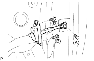
- Torque:
- Bolt (A)
- 29 N*m { 296 kgf*cm, 21 ft.*lbf }
- Bolt (B)
- 5.5 N*m { 56 kgf*cm, 49 in.*lbf }
-
-
INSTALL FRONT DOOR BELT MOULDING ASSEMBLY
-
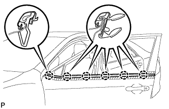
Engage the 6 claws to install the front door belt moulding assembly.
-
-
INSTALL FRONT DOOR GLASS RUN
-
Install the front door glass run.
-
-
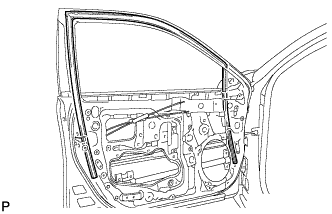
INSTALL FRONT DOOR GLASS SUB-ASSEMBLY
-
Connect the cable to the negative (-) battery terminal.
-
Connect the power window regulator master switch assembly and move the front door glass sub-assembly so that the door glass bolts can be seen.
-
Disconnect the cable from the negative (-) battery terminal.
CAUTION:
Wait at least 90 seconds after disconnecting the cable from the negative (-) battery terminal to disable the SRS system.
Note
When disconnecting the cable, some systems need to be initialized after the cable is reconnected Click here.
-
Disconnect the power window regulator master switch assembly.
-
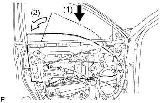
Insert the front door glass sub-assembly into the front door panel along the front door glass run as indicated by the arrows, in the order shown in the illustration.
-
Install the front door glass sub-assembly with the 2 bolts.
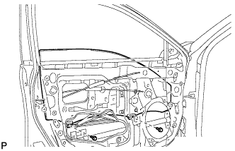
- Torque:
- 8.0 N*m { 82 kgf*cm, 71 in.*lbf }
-
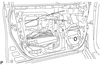
Install the grommet.
-
-
INSTALL FRONT DOOR SERVICE HOLE COVER
-
Apply new butyl tape to the front door panel.
-
Pass the front door lock remote control cable assembly and front door inside locking cable assembly through a new front door service hole cover.
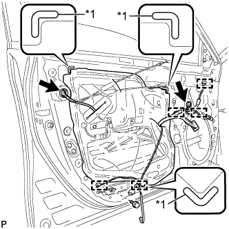
Text in Illustration *1 Reference Point -
Attach the front door service hole cover according to the reference points on the front door panel.
Note
Securely install the front door service hole cover preventing wrinkles and air bubbles.
-
Engage the 5 clamps.
-
Install the bolt.
- Torque:
- 8.0 N*m { 82 kgf*cm, 71 in.*lbf }
-
Connect each connector.
-
-
INSTALL DOOR SIDE AIRBAG SENSOR
-
Check that the ignition switch is off.
-
Check that the cable is disconnected from the negative (-) battery terminal.
CAUTION:
Wait at least 90 seconds after disconnecting the cable from the negative (-) battery terminal to disable the SRS system.
-
Before connecting the connector, check that the position of the white housing lock is correct as shown in the illustration.
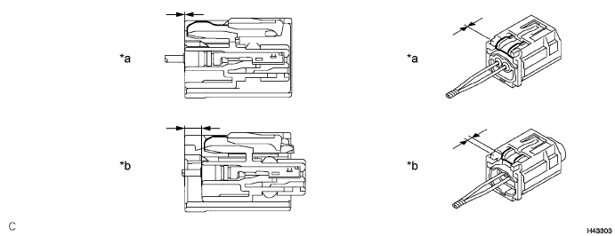
Text in Illustration *a Incorrect *b Correct -
Insert the pin (stopper) into the door hole and install the door side airbag sensor to the front door panel with the bolt.
- Torque:
- 9.0 N*m { 92 kgf*cm, 80 in.*lbf }
Note
-
If the door side airbag sensor has been dropped, or there are any cracks, dents or other defects in the case or connector, replace it with a new one.
-
When installing the door side airbag sensor, be careful that the SRS wiring does not interfere with or is not pinched between other parts.
-
Make sure that the pin (stopper) is securely inserted into the body hole.
-
Tighten the bolt while holding the door side airbag sensor because the door side airbag sensor pin (stopper) is easily damaged.
-
Connect the connector to the door side airbag sensor.
Note
When connecting any airbag connector, take care not to damage the airbag wire harness.
-
Be sure to engage the connectors until they are locked (when locking, make sure that a click sound can be heard).
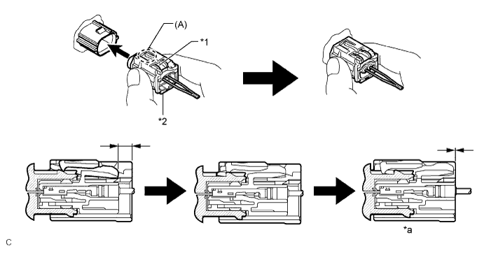
Text in Illustration *1 White Housing Lock *2 Yellow CPA *a Connection is Completed - - Tech Tips
When engaged, the white housing lock will slide. Be sure not to hold the white housing lock and part (A), as it may result in an insecure fit.
-
-
Check that there is no looseness in the installation parts of the door side airbag sensor.
-
-
INSTALL OUTER REAR VIEW MIRROR ASSEMBLY
-
CONNECT CABLE TO NEGATIVE BATTERY TERMINAL
Note
When disconnecting the cable, some systems need to be initialized after the cable is reconnected Click here.
-
INITIALIZE POWER WINDOW CONTROL SYSTEM (for Driver Side)
-
INSPECT POWER WINDOW OPERATION
-
INSPECT SRS WARNING LIGHT