INSTRUMENT PANEL SAFETY PAD REMOVAL

-
PRECAUTION
Note
After turning the ignition switch off, waiting time may be required before disconnecting the cable from the negative (-) battery terminal. Therefore, make sure to read the disconnecting the cable from the negative (-) battery terminal notices before proceeding with work Click here.
-
DISCONNECT CABLE FROM NEGATIVE BATTERY TERMINAL
CAUTION:
Wait at least 90 seconds after disconnecting the cable from the negative (-) battery terminal to disable the SRS system.
Note
When disconnecting the cable, some systems need to be initialized after the cable is reconnected Click here.
-
REMOVE FRONT DOOR SCUFF PLATE LH
-
Disengage the 10 claws and remove the front door scuff plate LH.
-
-
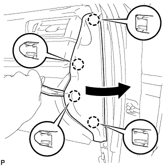
REMOVE COWL SIDE TRIM SUB-ASSEMBLY LH
-
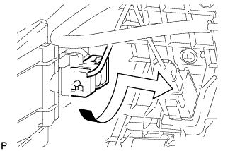
Remove the clip.
-
Disengage the 2 clips and remove the cowl side trim sub-assembly LH.
-
-
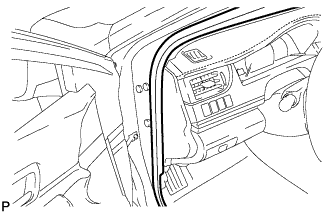
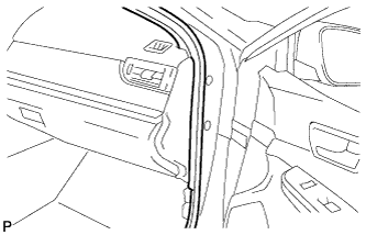
DISCONNECT FRONT DOOR OPENING TRIM WEATHERSTRIP LH
-
Disconnect the front door opening trim weatherstrip LH.
-
-
REMOVE INSTRUMENT SIDE PANEL LH
-
Using a moulding remover, disengage the 4 claws as shown in the illustration.
-
Disengage the 3 guides and remove the instrument side panel LH as shown in the illustration.
-
-
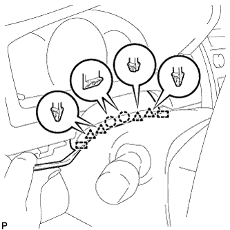
REMOVE NO. 1 INSTRUMENT CLUSTER FINISH PANEL GARNISH
-
Disengage the 3 clips to remove the No. 1 instrument cluster finish panel garnish as shown in the illustration.
-
-
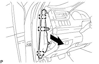
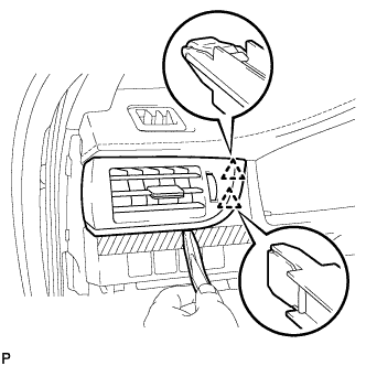
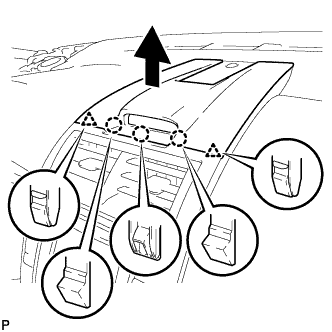
REMOVE NO. 1 INSTRUMENT PANEL REGISTER ASSEMBLY
-
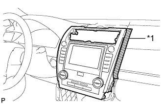
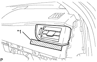
Apply protective tape to the area shown in the illustration.
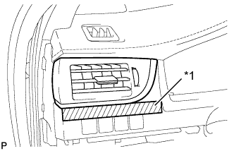
Text in Illustration *1 Protective Tape -
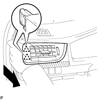
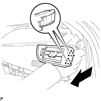
Disengage the 2 clips as shown in the illustration.
-
Using a moulding remover, disengage the 2 clips to remove the No. 1 instrument panel register assembly.
-
-
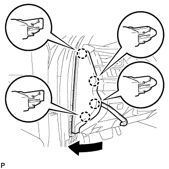
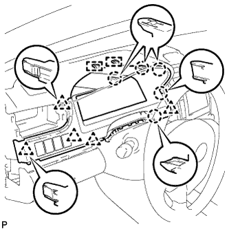
REMOVE INSTRUMENT CLUSTER FINISH PANEL ASSEMBLY
-
Operate the tilt and telescopic lever to fully extend and lower the steering column assembly.
-
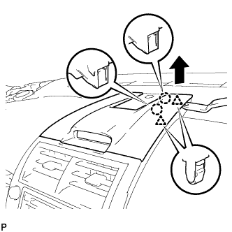
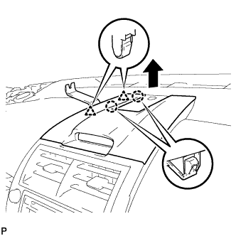
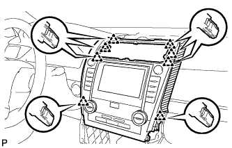
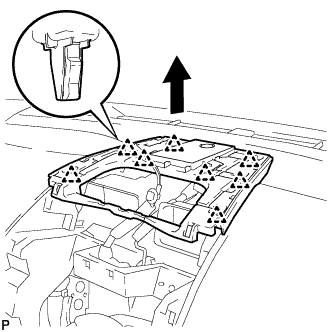
Using a moulding remover, disengage the 2 claws, 4 clips and 2 guides.
-
Disengage the 5 claws, 5 clips and 2 guides.
-
Disconnect each connector.
-
Remove the instrument cluster finish panel assembly as shown in the illustration.
-
-
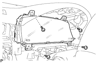
REMOVE COMBINATION METER ASSEMBLY
-
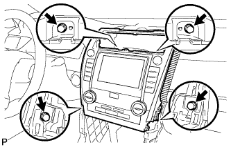
Remove the 4 screws.
-
Disengage the wire harness clamp.
-
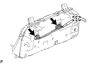
Disconnect the 2 connectors to remove the combination meter assembly.
-
-
REMOVE FRONT PANEL GARNISH LH
-
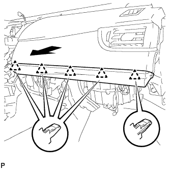
Disengage the 3 claws, 2 clips and 8 guides to remove the front panel garnish LH.
-
-
DISCONNECT HOOD LOCK CONTROL LEVER SUB-ASSEMBLY
-
Disengage the claw and 2 guides to disconnect the hood lock control lever sub-assembly.
-
-
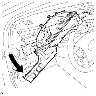
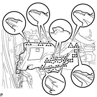
REMOVE LOWER NO. 1 INSTRUMENT PANEL FINISH PANEL ASSEMBLY
-
Remove the bolt <B> and screw <C> or <D>.
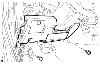
-
Disengage the 4 claws, 9 clips and 3 guides to remove the lower No. 1 instrument panel finish panel assembly.
-
-
REMOVE FRONT PANEL GARNISH RH
-
Disengage the 3 claws, 2 clips and 8 guides to remove the front panel garnish RH.
-
-
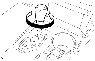
REMOVE SHIFT LEVER KNOB SUB-ASSEMBLY
-
Turn the shift lever knob sub-assembly counterclockwise and remove the shift lever knob sub-assembly.
-
-
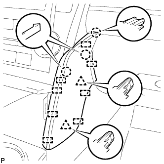
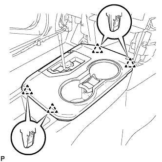
REMOVE REAR CONSOLE UPPER PANEL SUB-ASSEMBLY
-
Move the shift lever to N.
-
Disengage the 4 clips.
-
w/ Seat heater System:
-
Disconnect the 2 connectors.
-
-
Disconnect the connector and remove the rear console upper panel sub-assembly.
-
-
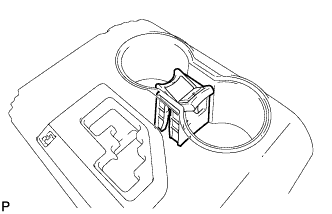
REMOVE CONSOLE BOX CUP HOLDER
-
Remove the console box cup holder from the rear console upper panel sub-assembly.
-
-
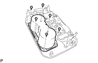
REMOVE INSTRUMENT PANEL CUP HOLDER TRAY
-
Remove the 6 screws <E> and instrument panel cup holder tray.
-
Remove the front console upper panel garnish.
-
-
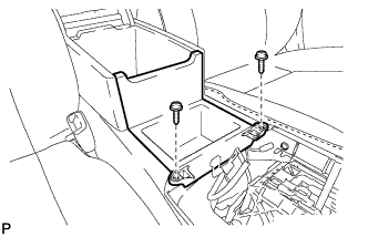
REMOVE UPPER CONSOLE BOX SUB-ASSEMBLY
-
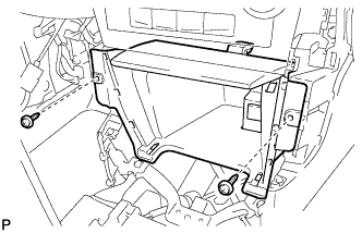
Remove the 2 screws.
-
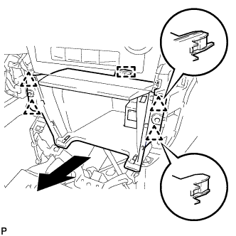
Disengage the 4 clips and remove the upper console box sub-assembly as shown in the illustration.
-
w/ Power Outlet Socket:
-
Disengage the clamp.
-
Disconnect the connector to remove the upper console box sub-assembly.
-
-
-
REMOVE NO. 4 CONSOLE BOX DUCT (w/ Rear Register Duct)
-
Disengage the claw and remove the No. 4 console box duct.
-
-
REMOVE CONSOLE BOX CARPET
-
Remove the console box carpet.
-
-
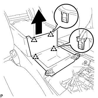
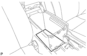
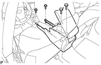
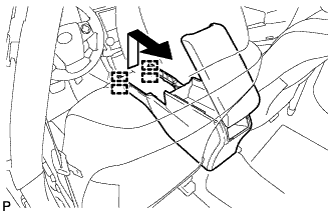
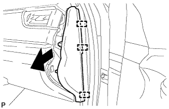
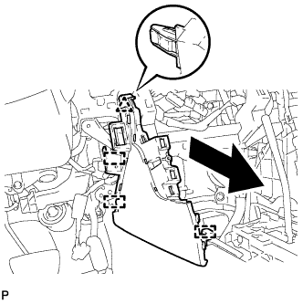
REMOVE REAR CONSOLE BOX ASSEMBLY
-
Remove the 2 bolts and 2 screws.
-
Pull the rear console box assembly in the direction indicated by the arrow to disengage the 4 guides and remove the rear console box assembly.
-
-
REMOVE CENTER INSTRUMENT CLUSTER FINISH PANEL ASSEMBLY
-
Using a moulding remover, disengage the 2 claws and 2 clips as shown in the illustration.
-
Using a moulding remover, disengage the 2 claws and 2 clips as shown in the illustration.
-
Disengage the 3 claws and 2 clips as shown in the illustration.
-
Disengage the clamp.
-
Disconnect the connector to remove the center instrument cluster finish panel assembly.
-
-
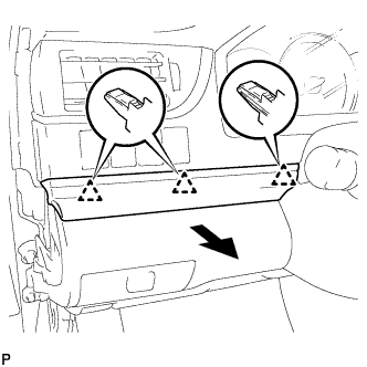
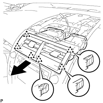
REMOVE NO. 2 INSTRUMENT PANEL REGISTER ASSEMBLY
-
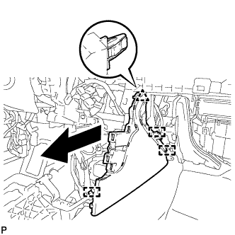
Pull the No. 2 instrument panel register assembly in the direction indicated by the arrow to disengage the 6 clips to remove the No. 2 instrument panel register assembly.
-
-
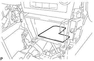
REMOVE BOX BOTTOM MAT
-
Remove the box bottom mat.
-
-
REMOVE UPPER CONSOLE PANEL SUB-ASSEMBLY
-
Remove the 2 screws <C> or <D>.
-
Disengage the 4 clips and guide as shown in the illustration.
-
Disconnect each connector to remove the upper console panel sub-assembly.
-
-
REMOVE RADIO RECEIVER ASSEMBLY WITH AIR CONDITIONING CONTROL ASSEMBLY (for Radio Receiver Type)
-
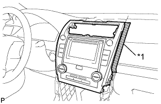
Apply protective tape to the area shown in the illustration.
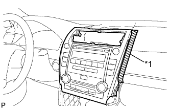
Text in Illustration *1 Protective Tape -
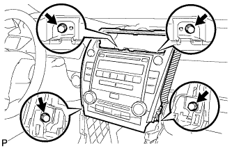
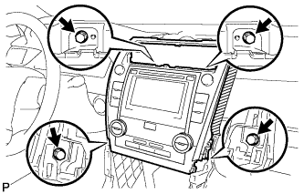
Remove the 4 bolts.
-
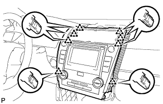
Pull the radio receiver assembly with air conditioning control assembly toward the rear of the vehicle and disengage the 8 clips.
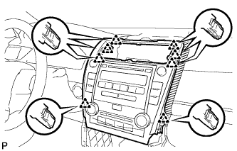
-
Disconnect each connector and remove the radio receiver assembly with air conditioning control assembly.
-
-
REMOVE RADIO RECEIVER ASSEMBLY WITH AIR CONDITIONING CONTROL ASSEMBLY (for Radio and Display Type)
-
Apply protective tape to the area shown in the illustration.
Text in Illustration *1 Protective Tape -
Remove the 4 bolts.
-
Pull the radio receiver assembly with air conditioning control assembly toward the rear of the vehicle and disengage the 8 clips.
-
Disconnect each connector and remove the radio receiver assembly with air conditioning control assembly.
Tech Tips
w/ Navigation System:Do not disconnect the extension module connector.
-
-
REMOVE NAVIGATION RECEIVER ASSEMBLY WITH AIR CONDITIONING CONTROL ASSEMBLY (for Navigation Receiver Type)
-
Apply protective tape to the area shown in the illustration.
Text in Illustration *1 Protective Tape -
Remove the 4 bolts.
-
Pull the navigation receiver assembly with air conditioning control assembly toward the rear of the vehicle and disengage the 8 clips.
-
Disconnect each connector and remove the navigation receiver assembly with air conditioning control assembly.
-
-
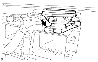
REMOVE NO. 1 SPEAKER OPENING COVER ASSEMBLY
-
Disengage the 8 clips as shown in the illustration.
-
Disconnect the connector to remove the No. 1 speaker opening cover assembly.
-
-
REMOVE FRONT NO. 3 SPEAKER ASSEMBLY (for 10 Speakers)
-
Remove the 2 screws.
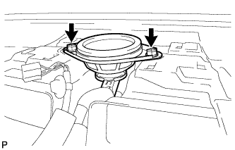
-
Lift the front No. 3 speaker assembly and disconnect the connector to remove the speaker.
Note
Do not touch the speaker cone.
-
-
REMOVE FRONT DOOR SCUFF PLATE RH
Tech Tips
Use the same procedure as for the LH side Click here.
-
REMOVE COWL SIDE TRIM SUB-ASSEMBLY RH
Tech Tips
Use the same procedure as for the LH side Click here.
-
DISCONNECT FRONT DOOR OPENING TRIM WEATHERSTRIP RH
-
Disconnect the front door opening trim weatherstrip RH.
-
-
REMOVE INSTRUMENT SIDE PANEL RH
-
Using a moulding remover, disengage the 4 claws as shown in the illustration.
-
Disengage the 3 guides to remove the instrument side panel RH as shown in the illustration.
-
-
REMOVE NO. 2 INSTRUMENT PANEL UNDER COVER SUB-ASSEMBLY
-
Disengage the 4 claws.
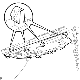
-
Disengage the 2 guides to remove the No. 2 instrument panel under cover sub-assembly.
-
-
REMOVE LOWER NO. 2 INSTRUMENT PANEL AIRBAG ASSEMBLY
CAUTION:
When storing the lower No. 2 instrument panel airbag assembly, keep the airbag deployment side facing upward.
-
Check that the ignition switch is off.
-
Check that the cable is disconnected from the negative (-) battery terminal.
CAUTION:
Wait at least 90 seconds after disconnecting the cable from the negative (-) battery terminal to disable the SRS system.
-
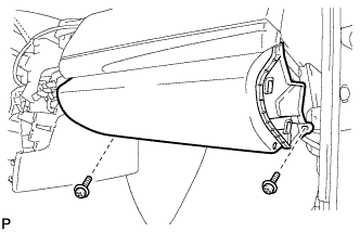
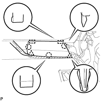
Remove the 3 bolts.
-
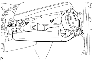
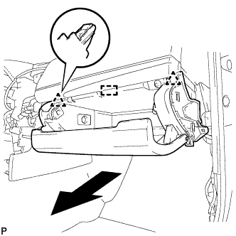
Disengage the 3 claws to remove the lower No. 2 instrument panel airbag assembly.
Note
When removing the lower No. 2 instrument panel airbag assembly, do not pull the airbag wire harness.
-
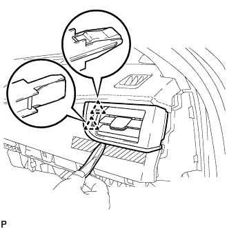
Using a screwdriver with the tip wrapped with protective tape, release the airbag connector lock.
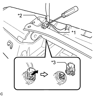
Text in Illustration *1 Protective Tape *2 Airbag Connector *3 Airbag Connector Lock -
Disconnect the airbag connector to remove the lower No. 2 instrument panel airbag assembly.
Note
When disconnecting any airbag connector, take care not to damage the airbag wire harness.
-
-
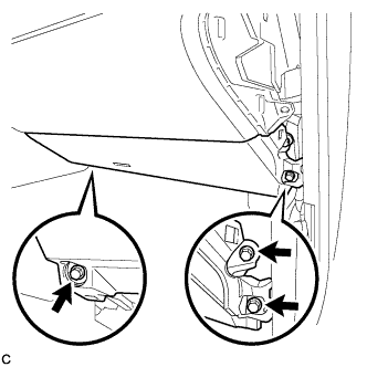
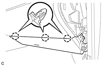
REMOVE LOWER INSTRUMENT PANEL SUB-ASSEMBLY
-
Remove the 2 screws <C> or <D>.
-
Open the lower instrument panel door.
-
Remove the 3 screws <C> or <D>.
-
Disengage the 2 clips and guide.
-
Disengage the glove compartment light as shown in the illustration.
-
Disconnect each connector and remove the lower instrument panel sub-assembly.
-
-
REMOVE NO. 2 INSTRUMENT CLUSTER FINISH PANEL GARNISH
-
Disengage the 5 clips to remove the No. 2 instrument cluster finish panel garnish as shown in the illustration.
-
-
REMOVE NO. 3 INSTRUMENT PANEL REGISTER ASSEMBLY
-
Apply protective tape to the area shown in the illustration.
Text in Illustration *1 Protective Tape -
Disengage the 2 clips as shown in the illustration.
-
Using a moulding remover, disengage the 2 clips to remove the No. 3 instrument panel register assembly.
-
-
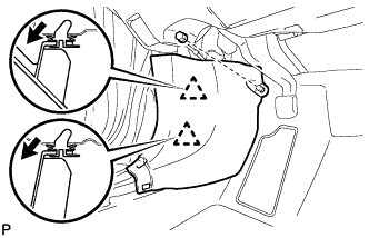
REMOVE FRONT PILLAR GARNISH LH
-
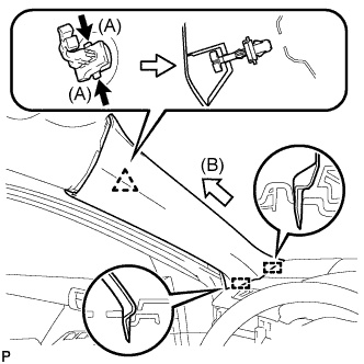
Pull the upper part of the garnish toward the inside of the cabin and disengage the garnish from the base of the 2 clips.

Text in Illustration *1 Front Pillar Garnish Clip Tech Tips
Make the front pillar garnish LH hang down from the front pillar garnish clip.
-
While pushing the tabs on the front pillar garnish clip in the direction indicated by the arrow (A) shown in the illustration, disengage the front pillar garnish clip.
-
Pull the garnish in the direction indicated by the arrow (B) shown in the illustration to disengage the 2 guides and remove the front pillar garnish LH.
-
Protect the curtain shield airbag assembly.
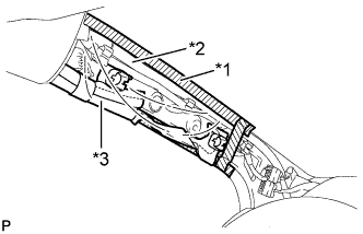
Text in Illustration *1 Adhesive Tape *2 Protective Cover *3 Curtain Shield Airbag Assembly -
Cover the airbag with a piece of cloth or nylon and secure the edges of the cover with tape as shown in the illustration.
Note
Cover the curtain shield airbag with a protective cover as soon as the front pillar garnish is removed.
-
-
-
REMOVE NO. 1 INSTRUMENT PANEL SPEAKER PANEL SUB-ASSEMBLY
-
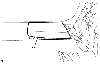
Apply protective tape to the area shown in the illustration.
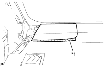
Text in Illustration *1 Protective Tape -
Using a moulding remover, disengage the 2 clips and 3 claws.
-
Disengage the 2 guides to remove the No.1 instrument panel speaker panel sub-assembly.
-
-
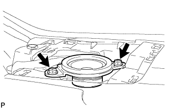
REMOVE FRONT NO. 2 SPEAKER ASSEMBLY (for LH Side)
-
Remove the 2 screws.
-
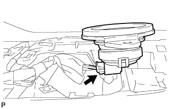
Lift the front No. 2 speaker assembly and disconnect the connector to remove the speaker.
Note
Do not touch the speaker cone.
-
-
REMOVE FRONT PILLAR GARNISH RH
Tech Tips
Use the same procedure as for the LH side Click here.
-
REMOVE NO. 2 INSTRUMENT PANEL SPEAKER PANEL SUB-ASSEMBLY
-
Apply protective tape to the area shown in the illustration.
Text in Illustration *1 Protective Tape -
Using a moulding remover, disengage the 2 clips and 3 claws.
-
Disengage the 2 guides to remove the No. 2 instrument panel speaker panel sub-assembly.
-
-
REMOVE FRONT NO. 2 SPEAKER ASSEMBLY (for RH Side)
Tech Tips
Use the same procedure as for the LH side Click here.
-
REMOVE LOWER INSTRUMENT PANEL FINISH PANEL ASSEMBLY
-
Disengage the 4 clips to remove the lower instrument panel finish panel assembly.
-
w/ Smart Key System:
-
Disconnect the connector.
-
-
-
REMOVE FRONT NO. 2 CONSOLE BOX INSERT
-
Disengage the 2 claws to disconnect the room temperature sensor from the front No. 2 console box insert.
-
Remove the 2 screws <C> or <D>.
-
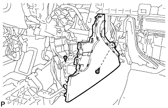
Disengage the clip and 3 guides to remove the front No. 2 console box insert as shown in the illustration.
-
-
REMOVE CONSOLE BOX INSERT
-
Remove the 2 screws <C> or <D>.
-
Disengage the clip and 3 guides to remove the console box insert as shown in the illustration.
-
-
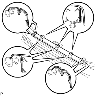
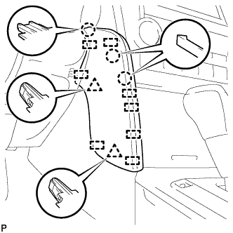
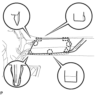
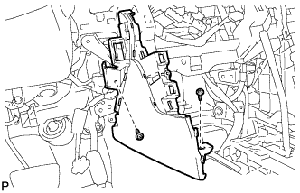
REMOVE NO. 1 INSTRUMENT PANEL GARNISH SUB-ASSEMBLY
-
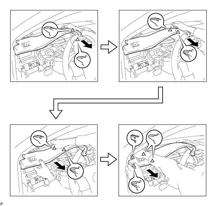
Disengage the 10 clips to remove the No.1 instrument panel garnish sub-assembly as shown in the illustration.
-
-
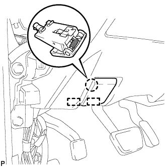
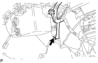
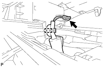
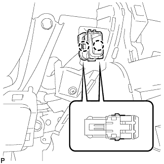
DISCONNECT NO. 2 INSTRUMENT PANEL WIRE
-
Check that the ignition switch is off.
-
Check that the cable is disconnected from the negative (-) battery terminal.
CAUTION:
Wait at least 90 seconds after disconnecting the cable from the negative (-) battery terminal to disable the SRS system.
-
Slide the slider to release the lock, and then disconnect the connector.
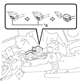
Text in Illustration *a Slider Note
When disconnecting any airbag connector, take care not to damage the airbag wire harness.
-
-
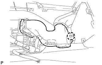
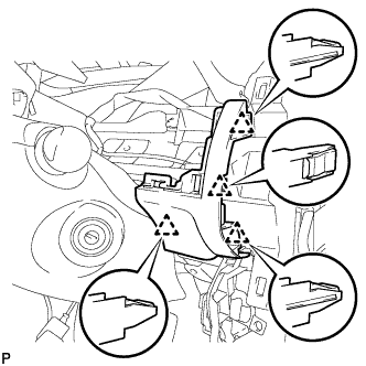
REMOVE INSTRUMENT PANEL SAFETY PAD ASSEMBLY
-
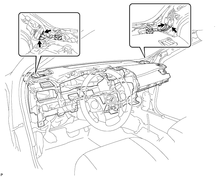
Disconnect each connector.
-
Disengage each clamp.
-
Remove the 2 passenger airbag bolts <A>.
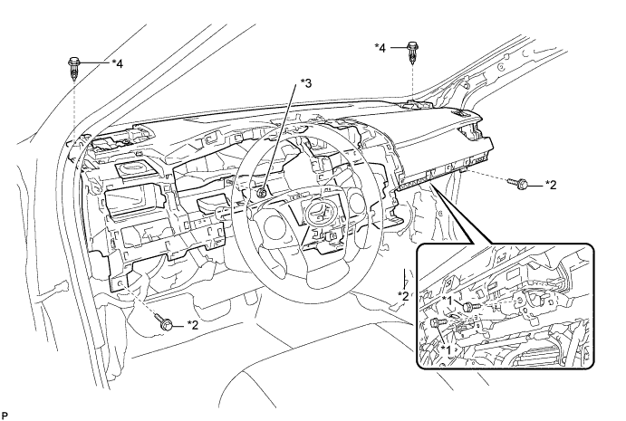
Text in Illustration *1 Passenger Airbag Bolt <A> *2 Bolt <B> *3 Nut <F> or <G> *4 Clip -
Remove the 3 bolts <B> and nut <F> or <G>.
-
Remove the 2 clips.
-
Disengage the 5 guides and remove the instrument panel safety pad assembly as shown in the illustration.
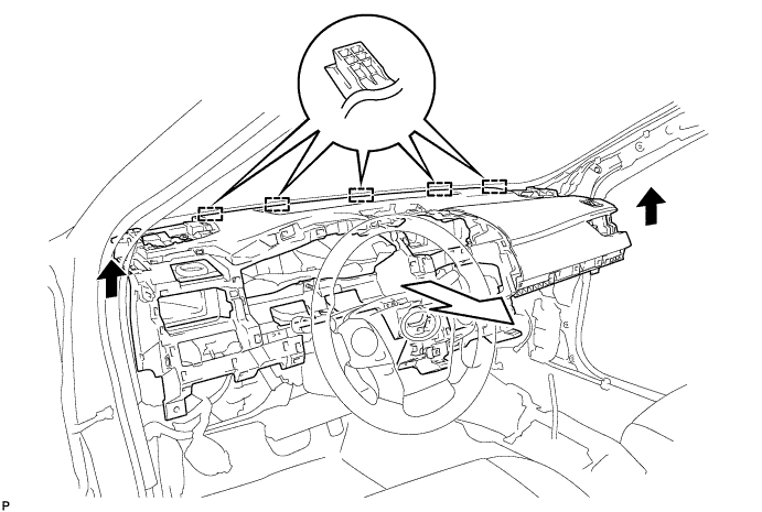
Note
-
Do not damage the instrument panel safety pad assembly.
-
Do not allow the wire harnesses to interfere with the surrounding parts.
-
-