METER / GAUGE SYSTEM TERMINALS OF ECU

-
COMBINATION METER ASSEMBLY
-
Measure the voltage and resistance according to the value(s) in the table below.
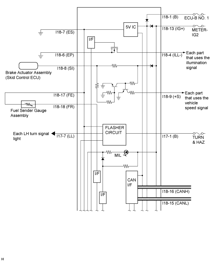
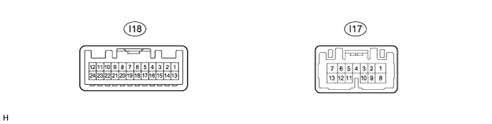
Terminal No. (Symbol) Wiring Color Terminal Description Condition Specified Condition I18-1 (B) - Body ground W - Body ground Battery Always 11 to 14 V I18-4 (ILL-) - Body ground SB - Body ground Illumination signal Light control switch off Below 1 V Light control switch on TAIL or HEAD position Pulse generation I18-6 (EP) - Body Ground W-B - Body ground Ground Always Below 1 Ω I18-7 (ES) - Body Ground BR - Body ground Ground Always Below 1 Ω I18-8 (SI) - Body ground P - Body ground Speed signal for other system (Input) Ignition switch ON, wheel being rotated Pulse generation
(See waveform 1)
I18-9 (+S) - Body ground V - Body ground Speed signal for other system (Output) Ignition switch ON, wheel being rotated Pulse generation
(See waveform 1)
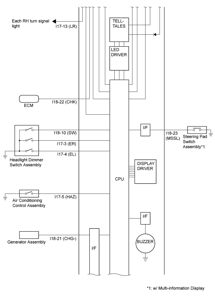
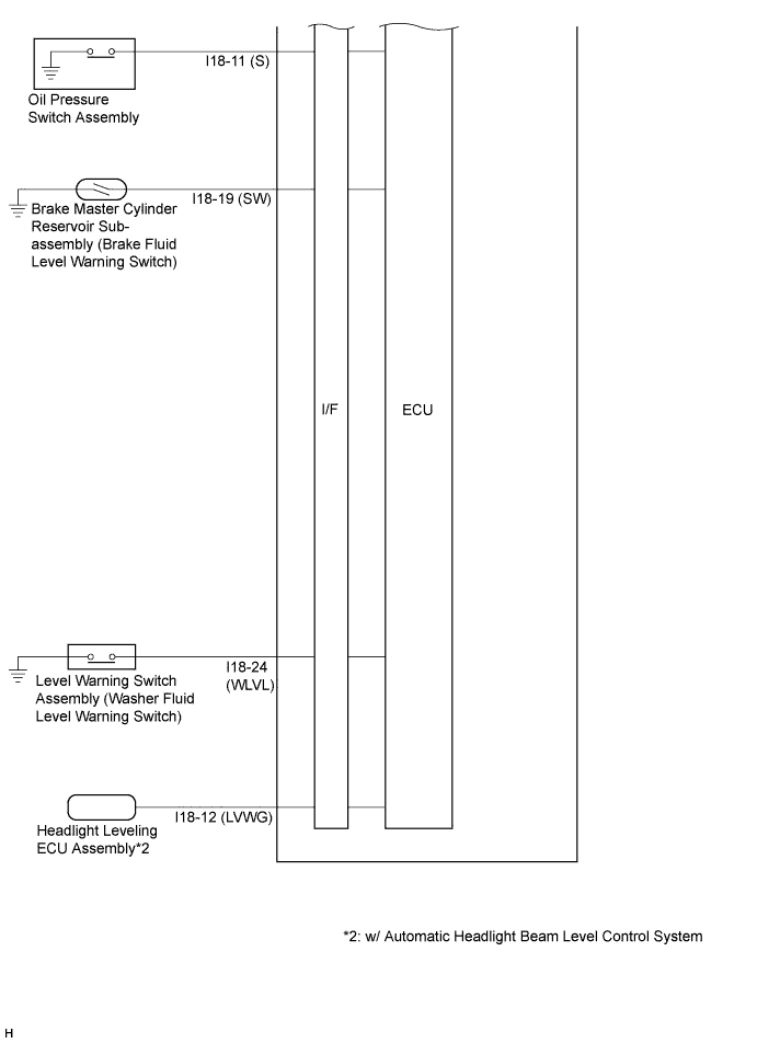
I18-10 (SW) - Body ground G - Body ground Turn switch signal Ignition switch ON, turn LH and RH switch off 11 to 14 V Ignition switch ON, turn LH or RH switch on Below 1 V I18-11 (S) - Body ground B - Body ground Oil pressure signal Ignition switch ON, oil pressure warning light off 9 to 15 V Ignition switch ON, washer warning light on Below 1 V I18-12 (LVWG)*1 - Body ground P - Body ground Headlight leveling signal Ignition switch ON, leveling indicator light off 11 to 14 V Ignition switch ON, leveling indicator light on Below 1 V I18-13 (IG+) - Body ground L - Body ground Ignition switch signal Ignition switch off Below 1 V Ignition switch ON 11 to 14 V I18-15 (CANL) - Body ground W - Body ground CAN communication line - - I18-16 (CANH) - Body ground R - Body ground CAN communication line - - I18-17 (FE) - I18-18 (FR) V - GR Fuel signal Ignition switch ON, fuel level not low 4 to 14 V Ignition switch ON, fuel level low 4 V or less I18-19 (SW) - Body ground B - Body ground Brake fluid level signal Ignition switch ON, brake warning light off 11 to 14 V Ignition switch ON, brake warning light on Below 1 V I18-21 (CHG-) - Body ground SB - Body ground Charge warning light signal Ignition switch ON, charge warning light off 11 to 14 V Ignition switch ON, charge warning light on Below 1 V I18-22 (CHK) - Body ground R - Body ground MIL (Check engine warning light) signal Ignition switch ON, MIL off 11 to 14 V Ignition switch ON, MIL on Below 1 V I18-23 (MSSL)*2 - Body ground L - Body ground Steering pad switch assembly (DISP switch) signal Ignition switch ON, DISP switch not pressed 4 to 5 V Ignition switch ON, DISP switch pressed Below 1 V I18-24 (WLVL) - Body ground LG - Body ground Washer fluid level signal Ignition switch ON, washer fluid level indicator light off 11 to 14 V Ignition switch ON, washer fluid level indicator light on Below 1 V I17-1 (B) - Body ground R - Body ground Battery Always 11 to 14 V I17-3 (ER) - Body ground P - Body ground Turn RH switch signal Ignition switch ON, RH turn switch off 11 to 14 V Ignition switch ON, RH turn switch on Below 1 V I17-4 (EL) - Body ground L - Body ground Turn LH switch signal Ignition switch ON, LH turn switch off 11 to 14 V Ignition switch ON, LH turn switch on Below 1 V I17-5 (HAZ) - Body ground W - Body ground Hazard warning switch signal Ignition switch ON, hazard warning switch off 11 to 14 V Ignition switch ON, hazard warning switch on Below 1 V I17-7 (LL) - Body ground R - Body ground Turn LH indicator light signal Turn LH indicator light off 11 to 14 V Turn LH indicator light blinks 11 to 14 V ←→ Below 1 V I17-13 (LR) - Body ground G - Body ground Turn RH indicator light signal Turn RH indicator light off 11 to 14 V Turn RH indicator light blinks 11 to 14 V ←→ Below 1 V -
*1: w/ Automatic Headlight Beam Level Control System
-
*2: w/ Multi-information Display
-
-
Waveform 1 (Reference):
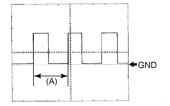
Item Condition Tool setting 5 V/DIV., 20 ms./DIV. Vehicle condition Wheel being rotated Tech Tips
When the system is functioning normally, one wheel revolution generates 4 pulses. As the vehicle speed increases, the width indicated by (A) in the illustration narrows.
-
-
CLOCK ASSEMBLY

-
Measure the voltage and resistance according to the value(s) in the table below.
Terminal No. (Symbol) Wiring Color Terminal Description Condition Specified Condition I59-1 (E) - Body ground W-B - Body ground Ground Always Below 1 Ω I59-5 (ILL+) - Body ground V - Body ground Illumination signal Light control switch off Below 1 V Light control switch TAIL or HEAD 11 to 14 V I59-6 (ACC) - Body ground P - Body ground Ignition switch signal Ignition switch off Below 1 V Ignition switch ACC 11 to 14 V I59-7 (B) - Body ground LG - Body ground Battery Always 11 to 14 V
-
-
COMBINATION METER ASSEMBLY INNER CIRCUIT