PARKING ASSIST MONITOR SYSTEM TERMINALS OF ECU

-
REAR TELEVISION CAMERA ASSEMBLY
-
Disconnect the T6 connector from the rear television camera assembly.

-
Measure the voltage of each terminal of the wire harness side connector.
Terminal No. (Symbol) Wiring Color Terminal Description Condition Specified Condition T6-6 (CB+) - Body ground B - Body ground Power source Engine switch on (IG)
Shift lever in R
5.5 to 7.05 V If the result is not as specified, there may be a malfunction on the wire harness side.
-
Measure the resistance according to the value(s) in the table below.
Terminal No. (Symbol) Wiring Color Terminal Description Condition Specified Condition T6-1 (CURT) - Body ground BR - Body ground Ground Always Below 1 Ω If the result is not as specified, there may be a malfunction on the wire harness side.
-
Reconnect the T6 connector to the rear television camera assembly.
-
Check for pulses between each terminal of the connector.
Terminal No. (Symbol) Wiring Color Terminal Description Condition Specified Condition T6-3 (CV+) - T6-2 (CV-) W - R Video signal Engine switch on (IG)
Shift lever in R
Camera lens not covered, displaying an image
Pulse generation
(See waveform 1)
Engine switch on (IG)
Shift lever in R
Camera lens covered, blacking out screen
Pulse generation
(See waveform 2)
Tech Tips
A waterproof connector is used for the rear television camera assembly. Therefore, inspect the waveform at the navigation ECU sub-assembly with the connector connected.
If the result is not as specified, the rear television camera assembly may have a malfunction.
-
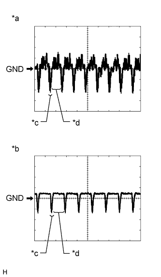
Reference (Oscilloscope waveform):
Tech Tips
A waterproof connector is used for the rear television camera assembly. Therefore, inspect the waveform at the navigation ECU sub-assembly with the connector connected.
-
Waveform 1 (camera lens is not covered, displaying an image)
Item Content Terminal No. (Symbol) T6-3 (CV+) - T6-2 (CV-) Tool Setting 200 mV/DIV., 50 μsec./DIV. Condition Engine switch on (IG), shift lever in R Tech Tips
The video waveform changes according to the image sent by the rear television camera assembly.
-
Waveform 2 (camera lens is covered, blacking out the screen)
Item Content Terminal No. (Symbol) T6-3 (CV+) - T6-2 (CV-) Tool Setting 200 mV/DIV., 50 μsec./DIV. Condition Engine switch on (IG), shift lever in R Tech Tips
The video waveform changes according to the image sent by the rear television camera assembly.
Text in Illustration *a Waveform 1 (camera lens not covered, displaying an image) *b Waveform 2 (camera lens covered, blacking out the screen) *c Synchronization Signal *d Video Waveform
-
-
-
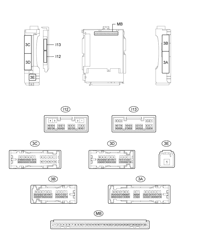
CHECK INSTRUMENT PANEL JUNCTION BLOCK ASSEMBLY AND MAIN BODY ECU (MULTIPLEX NETWORK BODY ECU)
-
Measure the voltage and check for pulses according to the value(s) in the table below.
Terminal No. (Symbol) Wiring Color Terminal Description Condition Specified Condition 3C-9 - Body ground W - Body ground Luggage compartment door courtesy light switch input Luggage compartment door open Below 1 V Luggage compartment door closed 11 to 14 V If the result is not as specified, the main body ECU (multiplex network body ECU) or instrument panel junction block assembly may have a malfunction.
-
-
NAVIGATION ECU SUB-ASSEMBLY (for Radio and Display Type with Intuitive Parking Assist System) Click here