NAVIGATION SYSTEM (for Radio and Display Type) Microphone Circuit between Microphone and Radio Receiver
DESCRIPTION
-
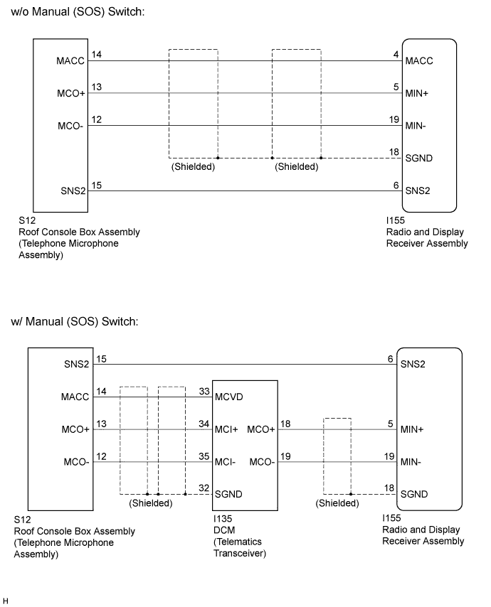
The radio and display receiver assembly and roof console box assembly (telephone microphone assembly) are connected to each other using the microphone connection detection signal lines.
-
Using this circuit, the radio and display receiver assembly sends power to the roof console box assembly (telephone microphone assembly), and the roof console box assembly (telephone microphone assembly) sends microphone signals to the radio and display receiver assembly (w/o Manual (SOS) Switch).
-
Using this circuit, the DCM (telematics transceiver) sends power to the roof console box assembly (telephone microphone assembly), and the roof console box assembly (telephone microphone assembly) sends microphone signals to the radio and display receiver assembly via the DCM (telematics transceiver) (w/ Manual (SOS) Switch).
WIRING DIAGRAM
INSPECTION PROCEDURE
Note
After replacing the radio and display receiver assembly of vehicles subscribed to pay-type satellite radio broadcasts, XM radio ID registration is necessary (w/ SDARS System).
PROCEDURE
-
CONFIRM MODEL
-
Choose the model to be inspected.
Result Model Proceed to w/o Manual (SOS) switch A w/ Manual (SOS) switch B
B 
CHECK HARNESS AND CONNECTOR (RADIO AND DISPLAY RECEIVER ASSEMBLY - ROOF CONSOLE BOX ASSEMBLY (TELEPHONE MICROPHONE ASSEMBLY)) Click here
A 
-
-
CHECK HARNESS AND CONNECTOR (RADIO AND DISPLAY RECEIVER ASSEMBLY - ROOF CONSOLE BOX ASSEMBLY (TELEPHONE MICROPHONE ASSEMBLY))
-
Disconnect the radio and display receiver assembly connector.
-
Disconnect the roof console box assembly (telephone microphone assembly) connector.
-
Measure the resistance according to the value(s) in the table below.
Standard Resistance Tester Connection Condition Specified Condition I155-4 (MACC) - S12-14 (MACC) Always Below 1 Ω I155-5 (MIN+) - S12-13 (MCO+) Always Below 1 Ω I155-19 (MIN-) - S12-12 (MCO-) Always Below 1 Ω I155-6 (SNS2) - S12-15 (SNS2) Always Below 1 Ω I155-4 (MACC) - Body ground Always 10 kΩ or higher I155-5 (MIN+) - Body ground Always 10 kΩ or higher I155-19 (MIN-) - Body ground Always 10 kΩ or higher I155-18 (SGND) - Body ground Always 10 kΩ or higher I155-6 (SNS2) - Body ground Always 10 kΩ or higher
NG 
REPAIR OR REPLACE HARNESS OR CONNECTOR
OK
-
-
INSPECT RADIO AND DISPLAY RECEIVER ASSEMBLY
-
Reconnect the radio and display receiver assembly connector.
-
Reconnect the roof console box assembly (telephone microphone assembly) connector.
-
Measure the voltage according to the value(s) in the table below.
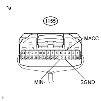
Standard Voltage Tester Connection Condition Specified Condition I155-4 (MACC) - Body ground Ignition switch ACC 4 to 6 V -
Measure the resistance according to the value(s) in the table below.
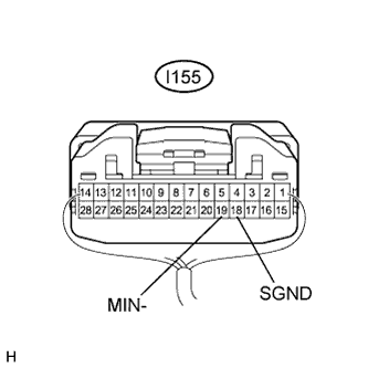
Standard Resistance Tester Connection Condition Specified Condition I155-18 (SGND) - Body ground Always Below 1 Ω I155-19 (MIN-) - Body ground Always Below 1 Ω -
Proceed to the next step based on the inspection result.
Result Result Proceed to NG A OK B Text in Illustration *a Component with harness connected
(Radio and Display Receiver Assembly)
B
INSPECT ROOF CONSOLE BOX ASSEMBLY (TELEPHONE MICROPHONE ASSEMBLY) Click here
A 
REPLACE RADIO AND DISPLAY RECEIVER ASSEMBLY Click here
-
-
CHECK HARNESS AND CONNECTOR (RADIO AND DISPLAY RECEIVER ASSEMBLY - ROOF CONSOLE BOX ASSEMBLY (TELEPHONE MICROPHONE ASSEMBLY))
-
Disconnect the radio and display receiver assembly connector.
-
Disconnect the roof console box assembly (telephone microphone assembly) connector.
-
Measure the resistance according to the value(s) in the table below.
Standard Resistance Tester Connection Condition Specified Condition I155-6 (SNS2) - S12-15 (SNS2) Always Below 1 Ω
NG
REPAIR OR REPLACE HARNESS OR CONNECTOR
OK
-
-
CHECK HARNESS AND CONNECTOR (RADIO AND DISPLAY RECEIVER ASSEMBLY - DCM (TELEMATICS TRANSCEIVER))
-
Disconnect the radio and display receiver assembly connector.
-
Disconnect the DCM (telematics transceiver) connector.
-
Measure the resistance according to the value(s) in the table below.
Standard Resistance Tester Connection Condition Specified Condition I155-5 (MIN+) - I135-18 (MCO+) Always Below 1 Ω I155-19 (MIN-) - I135-19 (MCO-) Always Below 1 Ω I155-5 (MIN+) - Body ground Always 10 kΩ or higher I155-19 (MIN-) - Body ground Always 10 kΩ or higher I155-18 (SGND) - Body ground Always 10 kΩ or higher
NG
REPAIR OR REPLACE HARNESS OR CONNECTOR
OK
-
-
CHECK HARNESS AND CONNECTOR (DCM (TELEMATICS TRANSCEIVER) - ROOF CONSOLE BOX ASSEMBLY (TELEPHONE MICROPHONE ASSEMBLY))
-
Disconnect the DCM (telematics transceiver) connector.
-
Disconnect the roof console box assembly (telephone microphone assembly) connector.
-
Measure the resistance according to the value(s) in the table below.
Standard Resistance Tester Connection Condition Specified Condition I135-33 (MCVD) - S12-14 (MACC) Always Below 1 Ω I135-34 (MCI+) - S12-13 (MCO+) Always Below 1 Ω I135-35 (MCI-) - S12-12 (MCO-) Always Below 1 Ω I135-33 (MCVD) - Body ground Always 10 kΩ or higher I135-34 (MCI+) - Body ground Always 10 kΩ or higher I135-35 (MCI-) - Body ground Always 10 kΩ or higher I135-32 (SGND) - Body ground Always 10 kΩ or higher
NG
REPAIR OR REPLACE HARNESS OR CONNECTOR
OK
-
-
INSPECT RADIO AND DISPLAY RECEIVER ASSEMBLY
-
Disconnect the DCM (telematics transceiver) connector.
-
Reconnect the radio and display receiver assembly connector.
-
Measure the resistance according to the value(s) in the table below.
Standard Resistance Tester Connection Condition Specified Condition I155-18 (SGND) - Body ground Always Below 1 Ω I155-19 (MIN-) - Body ground Always Below 1 Ω Text in Illustration *a Component with harness connected
(Radio and Display Receiver Assembly)
NG
REPLACE RADIO AND DISPLAY RECEIVER ASSEMBLY Click here
OK
-
-
INSPECT DCM (TELEMATICS TRANSCEIVER)
-
Reconnect the DCM (telematics transceiver) connector.
-
Measure the voltage according to the value(s) in the table below.
Standard Voltage Tester Connection Condition Specified Condition I135-33 (MCVD) - Body ground Ignition switch ACC 4 to 6 V -
Measure the resistance according to the value(s) in the table below.
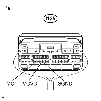
Standard Resistance Tester Connection Condition Specified Condition I135-35 (MCI-) - Body ground Always Below 1 Ω I135-32 (SGND) - Body ground Always Below 1 Ω Text in Illustration *a Component with harness connected
(DCM (Telematics Transceiver))
NG
REPLACE DCM (TELEMATICS TRANSCEIVER) Click here
OK
-
-
INSPECT ROOF CONSOLE BOX ASSEMBLY (TELEPHONE MICROPHONE ASSEMBLY)
-
Disconnect the roof console box assembly (telephone microphone assembly) connector.
-
Measure the resistance according to the value(s) in the table below.
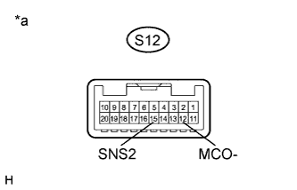
Standard Resistance Tester Connection Condition Specified Condition S12-15 (SNS2) - S12-12 (MCO-) Always Below 1 Ω Text in Illustration *a Component without harness connected
(Roof Console Box Assembly (Telephone Microphone Assembly))
NG
REPLACE ROOF CONSOLE BOX ASSEMBLY (TELEPHONE MICROPHONE ASSEMBLY) Click here
OK
-
-
INSPECT ROOF CONSOLE BOX ASSEMBLY (TELEPHONE MICROPHONE ASSEMBLY)
-
Reconnect the radio and display receiver assembly connector.
-
Reconnect the roof console box assembly (telephone microphone assembly) connector.
-
Reconnect the DCM (telematics transceiver) connector (w/ Manual (SOS) Switch).
-
Turn the ignition switch to ACC.
-
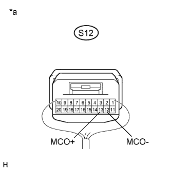
Connect an oscilloscope to terminals 13 (MCO+) and 12 (MCO-) of the roof console box assembly (telephone microphone assembly) connector.
-
Check the waveform of the telephone microphone assembly using the oscilloscope.
Result Result Proceed to A waveform synchronized with the voice input to the roof console box assembly (telephone microphone assembly) is output A A waveform synchronized with the voice input to the roof console box assembly (telephone microphone assembly) is not output B Text in Illustration *a Component with harness connected
(Roof Console Box Assembly (Telephone Microphone Assembly))
B
REPLACE ROOF CONSOLE BOX ASSEMBLY (TELEPHONE MICROPHONE ASSEMBLY) Click here
A
PROCEED TO NEXT SUSPECTED AREA SHOWN IN PROBLEM SYMPTOMS TABLE Click here
-