NAVIGATION SYSTEM (for Radio and Display Type) Mute Signal Circuit between Radio Receiver and Extension Module
DESCRIPTION
This circuit sends a signal to the extension module to mute noise. Because of that, the noise produced by changing the sound source ceases.
If there is an open in the circuit, noise can be heard from the speakers when changing the sound source.
If there is a short in the circuit, even though the extension module is functioning, no sound, or only an extremely faint sound, can be heard.
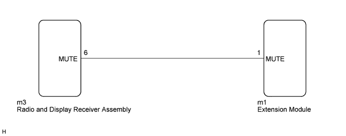
WIRING DIAGRAM
INSPECTION PROCEDURE
Note
After replacing the radio and display receiver assembly of vehicles subscribed to pay-type satellite radio broadcasts, XM radio ID registration is necessary (w/ SDARS System).
PROCEDURE
-
INSPECT EXTENSION MODULE
-
Measure the voltage according to the value(s) in the table below.
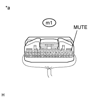
Standard Voltage Tester Connection Condition Specified Condition m1-1 (MUTE) - Body ground Ignition switch ACC, audio system is playing
→ Changing modes
Above 3.5 V
→ Below 1 V
Text in Illustration *a Component with harness connected
(Extension Module)
NG 
CHECK HARNESS AND CONNECTOR (RADIO AND DISPLAY RECEIVER ASSEMBLY - EXTENSION MODULE) Click here
OK 
PROCEED TO NEXT SUSPECTED AREA SHOWN IN PROBLEM SYMPTOMS TABLE Click here
-
-
CHECK HARNESS AND CONNECTOR (RADIO AND DISPLAY RECEIVER ASSEMBLY - EXTENSION MODULE)
-
Disconnect the radio and display receiver assembly connector.
-
Disconnect the extension module connector.
-
Measure the resistance according to the value(s) in the table below.
Standard Resistance Tester Connection Condition Specified Condition m3-6 (MUTE) - m1-1 (MUTE) Always Below 1 Ω m3-6 (MUTE) - Body ground Always 10 kΩ or higher
NG 
REPAIR OR REPLACE HARNESS OR CONNECTOR
OK 
-
-
INSPECT RADIO AND DISPLAY RECEIVER ASSEMBLY (OUTPUT SIGNAL)
-
Reconnect the radio and display receiver assembly connector.
-
Measure the voltage according to the value(s) in the table below.
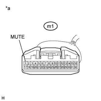
Standard Voltage Tester Connection Condition Specified Condition m1-1 (MUTE) - Body ground Ignition switch ACC, audio system is playing Above 3.5 V Text in Illustration *a Front view of wire harness connector
(to Extension Module)
NG
REPLACE RADIO AND DISPLAY RECEIVER ASSEMBLY Click here
OK
REPLACE EXTENSION MODULE Click here
-