NAVIGATION SYSTEM (for Radio and Display Type), Diagnostic DTC:B1579

| DTC Code | DTC Name |
|---|---|
| B1579 | Voice Recognition Microphone Disconnected |
DESCRIPTION
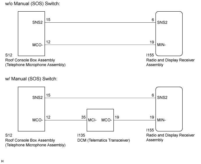
The radio and display receiver assembly and roof console box assembly (telephone microphone assembly) are connected to each other using the microphone connection detection signal lines.
This DTC is stored when a microphone connection detection signal line is disconnected.
| DTC Code | DTC Detection Condition | Trouble Area |
|---|---|---|
| B1579 | Telephone microphone signal is lost. |
|
-
*1: w/ Manual (SOS) Switch
WIRING DIAGRAM
INSPECTION PROCEDURE
Note
After replacing the radio and display receiver assembly of vehicles subscribed to pay-type satellite radio broadcasts, XM radio ID registration is necessary (w/ SDARS System).
PROCEDURE
-
INSPECT RADIO AND DISPLAY RECEIVER ASSEMBLY
-
Measure the resistance according to the value(s) in the table below.
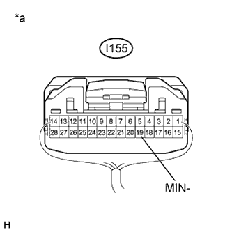
Standard Resistance Tester Connection Condition Specified Condition I155-19 (MIN-) - Body ground Always Below 1 Ω Text in Illustration *a Component with harness connected
(Radio and Display Receiver Assembly)
NG 
REPLACE RADIO AND DISPLAY RECEIVER ASSEMBLY Click here
OK 
-
-
CONFIRM MODEL
-
Choose the model to be inspected.
Result Model Proceed to w/ Manual (SOS) Switch A w/o Manual (SOS) Switch B
B 
CHECK HARNESS AND CONNECTOR (RADIO AND DISPLAY RECEIVER ASSEMBLY - ROOF CONSOLE BOX ASSEMBLY (TELEPHONE MICROPHONE ASSEMBLY)) Click here
A
-
-
CHECK HARNESS AND CONNECTOR (DCM (TELEMATICS TRANSCEIVER) - ROOF CONSOLE BOX ASSEMBLY (TELEPHONE MICROPHONE ASSEMBLY))
-
Disconnect the DCM (telematics transceiver) connector.
-
Disconnect the roof console box assembly (telephone microphone assembly) connector.
-
Measure the resistance according to the value(s) in the table below.
Standard Resistance Tester Connection Condition Specified Condition I135-35 (MCI-) - S12-12 (MCO-) Always Below 1 Ω I135-35 (MCI-) - Body ground Always 10 kΩ or higher
NG
REPAIR OR REPLACE HARNESS OR CONNECTOR
OK
-
-
CHECK HARNESS AND CONNECTOR (RADIO AND DISPLAY RECEIVER ASSEMBLY - DCM (TELEMATICS TRANSCEIVER))
-
Disconnect the radio and display receiver assembly connector.
-
Disconnect the DCM (telematics transceiver) connector.
-
Measure the resistance according to the value(s) in the table below.
Standard Resistance Tester Connection Condition Specified Condition I155-19 (MIN-) - I135-19 (MCO-) Always Below 1 Ω I155-19 (MIN-) - Body ground Always 10 kΩ or higher
NG
REPAIR OR REPLACE HARNESS OR CONNECTOR
OK
-
-
CHECK HARNESS AND CONNECTOR (RADIO AND DISPLAY RECEIVER ASSEMBLY - ROOF CONSOLE BOX ASSEMBLY (TELEPHONE MICROPHONE ASSEMBLY))
-
Disconnect the radio and display receiver assembly connector.
-
Disconnect the roof console box assembly (telephone microphone assembly) connector.
-
Measure the resistance according to the value(s) in the table below.
Standard Resistance Tester Connection Switch Condition Specified Condition I155-6 (SNS2) - S12-15 (SNS2) Always Below 1 Ω I155-6 (SNS2) - Body ground Always 10 kΩ or higher
NG
REPAIR OR REPLACE HARNESS OR CONNECTOR
OK
-
-
INSPECT DCM (TELEMATICS TRANSCEIVER)
-
Reconnect the DCM (telematics transceiver) connector.
-
Reconnect the radio and display receiver assembly connector.
-
Measure the resistance according to the value(s) in the table below.
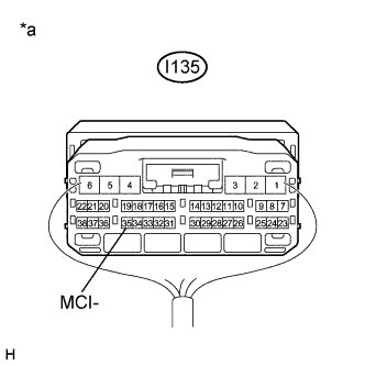
Standard Resistance Tester Connection Condition Specified Condition I135-35 (MCI-) - Body ground Always Below 1 Ω -
Proceed to the next step based on the inspection result.
Result Result Proceed to NG A OK B Text in Illustration *a Component with harness connected
(DCM (Telematics Transceiver))
B
INSPECT ROOF CONSOLE BOX ASSEMBLY (TELEPHONE MICROPHONE ASSEMBLY) Click here
A 
REPLACE DCM (TELEMATICS TRANSCEIVER) Click here
-
-
CHECK HARNESS AND CONNECTOR (RADIO AND DISPLAY RECEIVER ASSEMBLY - ROOF CONSOLE BOX ASSEMBLY (TELEPHONE MICROPHONE ASSEMBLY))
-
Disconnect the radio and display receiver assembly connector.
-
Disconnect the roof console box assembly (telephone microphone assembly) connector.
-
Measure the resistance according to the value(s) in the table below.
Standard Resistance Tester Connection Switch Condition Specified Condition I155-6 (SNS2) - S12-15 (SNS2) Always Below 1 Ω I155-19 (MIN-) - S12-12 (MCO-) Always Below 1 Ω I155-6 (SNS2) - Body ground Always 10 kΩ or higher I155-19 (MIN-) - Body ground Always 10 kΩ or higher
NG
REPAIR OR REPLACE HARNESS OR CONNECTOR
OK
-
-
INSPECT ROOF CONSOLE BOX ASSEMBLY (TELEPHONE MICROPHONE ASSEMBLY)
-
Measure the resistance according to the value(s) in the table below.
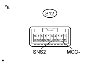
Standard Resistance Tester Connection Switch Condition Specified Condition S12-15 (SNS2) - S12-12 (MCO-) Always Below 1 Ω Text in Illustration *a Component without harness connected
(Roof Console Box Assembly (Telephone Microphone Assembly))
NG
REPLACE ROOF CONSOLE BOX ASSEMBLY (TELEPHONE MICROPHONE ASSEMBLY) Click here
OK
REPLACE RADIO AND DISPLAY RECEIVER ASSEMBLY Click here
-