POWER STEERING SYSTEM (for 2AR with Wireless Door Lock), Diagnostic DTC:C1511, C1512, C1513, C1514, C1517

| DTC Code | DTC Name |
|---|---|
| C1511 | Torque Sensor Circuit Malfunction |
| C1512 | Torque Sensor Circuit Malfunction |
| C1513 | Torque Sensor Circuit Malfunction |
| C1514 | Torque Sensor Power Supply Abnormal |
| C1517 | Torque Hold Abnormal |
DESCRIPTION
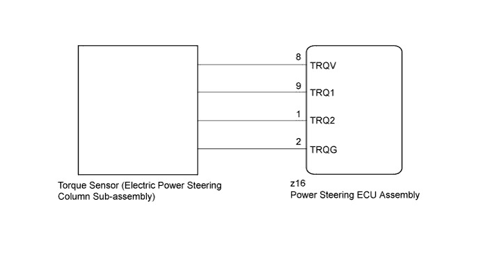
The torque sensor converts the rotation torque received from the steering wheel into electric signals and sends them to the power steering ECU assembly.
| DTC No. | DTC Detection Condition | Trouble Area |
|---|---|---|
| C1511 | Torque sensor malfunction |
|
| C1512 | ||
| C1513 | ||
| C1514 | ||
| C1517 |
WIRING DIAGRAM
INSPECTION PROCEDURE
Note
-
If the power steering ECU assembly has been replaced with a new one, perform assist map writing and torque sensor zero point calibration Click here.
-
If the electric power steering column sub-assembly has been replaced with a new one, perform torque sensor zero point calibration after performing the initialization of the torque sensor zero point value Click here.
PROCEDURE
-
CHECK CONNECTOR CONNECTION CONDITION
-
Check the connection condition of the torque sensor connector.
OK Torque sensor connector is securely connected to the power steering ECU assembly.
NG 
CONNECT CONNECTOR
OK 
-
-
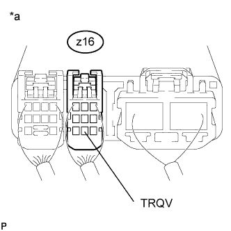
CHECK POWER STEERING ECU ASSEMBLY (TRQV VOLTAGE)
-
Start the engine.
-
Measure the voltage according to the value(s) in the table below.
Standard Voltage Tester Connection Condition Specified Condition z16-8 (TRQV) - Body ground Engine running 4.5 to 5.5 V Text in Illustration *a Component with harness connected
(Power Steering ECU Assembly)
NG
REPLACE POWER STEERING ECU ASSEMBLY Click here
OK
-
-
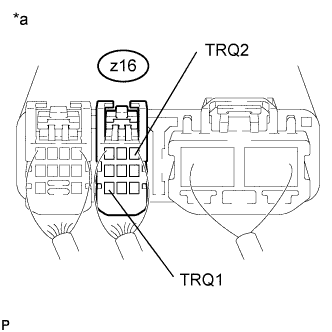
CHECK POWER STEERING ECU ASSEMBLY (TRQ1, TRQ2 VOLTAGE)
-
Start the engine.
-
Measure the voltage according to the value(s) in the table below.
Standard Voltage Tester Connection Condition (Steering Wheel Position) Specified Condition z16-9 (TRQ1) - Body ground Engine running
(Center position)
2.3 to 2.7 V z16-1 (TRQ2) - Body ground Engine running
(Center position)
2.3 to 2.7 V z16-9 (TRQ1) - Body ground Engine running
(Turned to right)
2.5 to 3.8 V z16-1 (TRQ2) - Body ground Engine running
(Turned to right)
1.2 to 2.5 V z16-9 (TRQ1) - Body ground Engine running
(Turned to left)
1.2 to 2.5 V z16-1 (TRQ2) - Body ground Engine running
(Turned to left)
2.5 to 3.8 V -
Under each condition, measure the voltage at terminals TRQ1 and TRQ2, and calculate the sum.
Standard Voltage Inspection Item Condition (Steering Wheel Position) Specified Condition Sum of voltage between z16-9 (TRQ1) and body ground and voltage between z16-1 (TRQ2) and body ground Engine running
Steering wheel not being turned (without load)
Between 4.75 V and 5.25 V Engine running
Steering wheel being turned to the right with vehicle stopped
Engine running
Steering wheel being turned to the left with vehicle stopped
Text in Illustration *a Component with harness connected
(Power Steering ECU Assembly)
NG
REPLACE ELECTRIC POWER STEERING COLUMN SUB-ASSEMBLY Click here
OK 
REPLACE POWER STEERING ECU ASSEMBLY Click here
-