POWER STEERING SYSTEM (for 2AR without Wireless Door Lock), Diagnostic DTC:C1524, C1555

| DTC Code | DTC Name |
|---|---|
| C1524 | Motor Circuit Malfunction |
| C1555 | Motor Relay Welding Failure |
DESCRIPTION
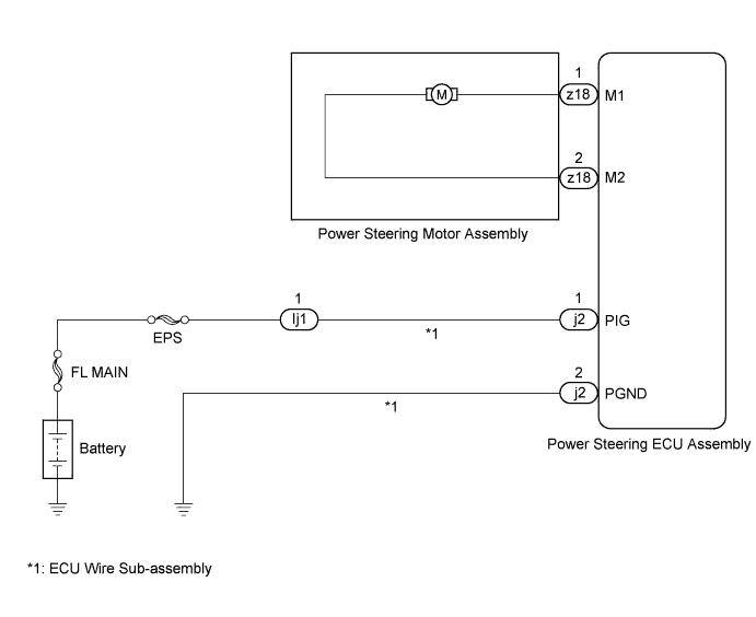
The power steering ECU assembly supplies current to the power steering motor assembly through the motor circuit.
| DTC No. | DTC Detection Condition | Trouble Area |
|---|---|---|
| C1524 | Short (or open) in motor circuit or abnormal voltage in motor circuit |
|
| C1555 | Predriver (Motor relay circuit) malfunction |
WIRING DIAGRAM
INSPECTION PROCEDURE
Note
If the power steering ECU assembly has been replaced with a new one, perform assist map writing and torque sensor zero point calibration Click here.
Tech Tips
Inspect the fuses for circuits related to this system before performing the following inspection procedure.
PROCEDURE
-
CHECK POWER STEERING ECU ASSEMBLY
-
Start the engine.
-
Measure the voltage according to the value(s) in the table below.
Standard Voltage Tester Connection Condition
(Steering Wheel Position)
Specified Condition z18-1 (M1) - Body ground Engine running
(Turned to right)
Below 1 V z18-1 (M1) - Body ground Engine running
(Turned to left)
9 to 16 V z18-2 (M2) - Body ground Engine running
(Turned to right)
9 to 16 V z18-2 (M2) - Body ground Engine running
(Turned to left)
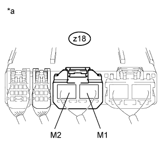
Below 1 V Text in Illustration *a Component with harness connected
(Power Steering ECU Assembly)
NG 
REPLACE POWER STEERING ECU ASSEMBLY Click here
OK 
-
-
CHECK POWER STEERING MOTOR ASSEMBLY
-
Disconnect the connector from the power steering ECU assembly.
-
Measure the resistance according to the value(s) in the table below.
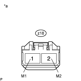
Standard Resistance Tester Connection Condition Specified Condition z18-1 (M1) - z18-2 (M2) Always 0.08 to 0.15 Ω z18-1 (M1) - Body ground Always 1 MΩ or higher z18-2 (M2) - Body ground Always 1 MΩ or higher Text in Illustration *a Front view of wire harness connector
(to Power Steering ECU Assembly)
NG
REPLACE POWER STEERING MOTOR ASSEMBLY Click here
OK 
REPLACE POWER STEERING ECU ASSEMBLY Click here
-