FRONT SUSPENSION MEMBER INSTALLATION

-
INSTALL HOLE PLUG
-
Install each hole plug to the front frame assembly.
-
-
INSTALL FRONT SUSPENSION MEMBER BODY MOUNTING REAR CUSHION LH
-
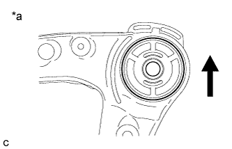
Temporarily install a new front suspension member body mounting rear cushion LH while confirming the installation direction.
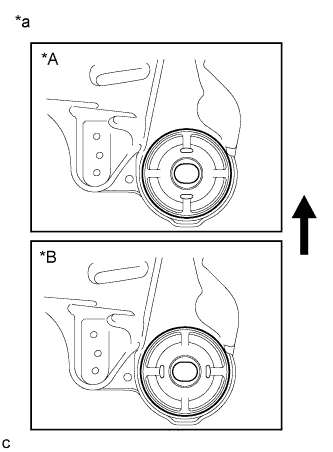
Text in Illustration *A Type A *B Type B *a View from Underneath 
Front of the Vehicle Note
Position the front suspension member body mounting rear cushion LH in the correct direction.
-
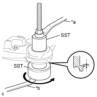
Install SST as shown in the illustration.
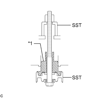
Text in Illustration *1 Front Suspension Member Body Mounting Rear Cushion LH - SST
- 09830-10010 ( 09830-01010, 09830-01020, 09830-01030, 09830-01060 )
-
Using SST, install the front suspension member body mounting rear cushion LH as shown in the illustration.
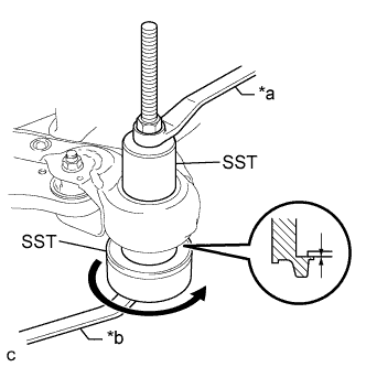
Text in Illustration *a Hold *b Turn Note
Check that there is no clearance between the front suspension member and the front suspension member body mounting rear cushion LH.
-
-
INSTALL FRONT SUSPENSION MEMBER BODY MOUNTING REAR CUSHION RH
-
Temporarily install a new front suspension member body mounting rear cushion RH while confirming the installation direction.
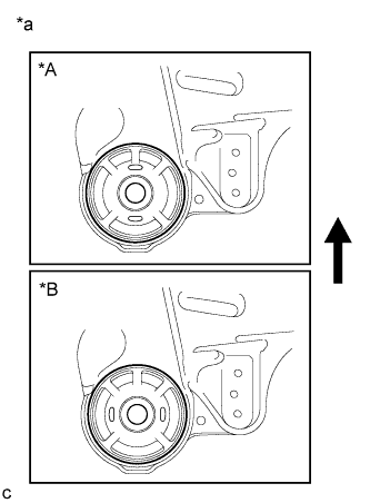
Text in Illustration *A Type A *B Type B *a View from Underneath Front of the Vehicle Note
Position the front suspension member body mounting rear cushion RH in the correct direction.
-
Install SST using the same procedure as the front suspension member body mounting rear cushion LH.
- SST
- 09830-10010 ( 09830-01010, 09830-01020, 09830-01030, 09830-01060 )
-
Using SST, install the front suspension member body mounting rear cushion RH.
- SST
- 09830-10010 ( 09830-01010, 09830-01020, 09830-01030, 09830-01060 )
Tech Tips
Perform the same procedure as the LH side.
-
-
INSTALL FRONT SUSPENSION MEMBER BODY MOUNTING FRONT CUSHION
-
Temporarily install a new front suspension member body mounting front cushion while confirming the installation direction.
Text in Illustration *a View from Underneath Front of the Vehicle Note
Position the front suspension member body mounting front cushion in the correct direction.
-
Install SST using the same procedure as the front suspension member body mounting rear cushion LH.
- SST
- 09830-10010 ( 09830-01010, 09830-01020, 09830-01030, 09830-01060 )
-
Using SST, install the front suspension member body mounting front cushion as shown in the illustration.
Text in Illustration *a Hold *b Turn - SST
- 09830-10010 ( 09830-01010, 09830-01020, 09830-01030, 09830-01060 )
Note
Check that there is no clearance between the front suspension member and the front suspension member body mounting front cushion.
-
-
INSTALL FRONT SUSPENSION MEMBER BODY MOUNTING REAR STOPPER
-
Install the 2 front suspension member body mounting rear stoppers to the front frame assembly.
-
-
INSTALL FRONT SUSPENSION MEMBER BODY MOUNTING FRONT STOPPER
-
Install the 2 front suspension member body mounting front stoppers to the front frame assembly.
-
-
INSTALL FRONT SUSPENSION MEMBER DYNAMIC DAMPER
-
Install the front suspension member dynamic damper to the front frame assembly with the 2 bolts.
- Torque:
- 29 N*m { 296 kgf*cm, 21 ft.*lbf }
-
-
INSTALL FRONT LOWER NO. 1 SUSPENSION ARM SUB-ASSEMBLY LH
-
Install the front lower arm bushing stopper to the front lower No. 1 suspension arm sub-assembly.
-
Install the front lower No. 1 suspension arm sub-assembly to the front frame assembly with the 3 bolts and nut in the order shown in the illustration.
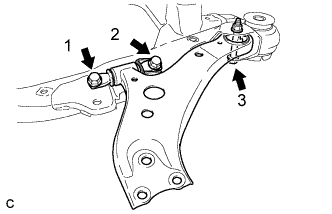
- Torque:
- Bolt 1, 2
- 200 N*m { 2039 kgf*cm, 148 ft.*lbf }
- Bolt 3
- 135 N*m { 1377 kgf*cm, 100 ft.*lbf }
Note
While keeping the nut from rotating, tighten the bolt.
-
-
INSTALL FRONT LOWER NO. 1 SUSPENSION ARM SUB-ASSEMBLY RH
Tech Tips
Perform the same procedure as the LH side.
-
INSTALL STEERING LINK ASSEMBLY
-
Install the steering link assembly with the 2 bolts and 2 nuts.
- Torque:
- 70 N*m { 714 kgf*cm, 52 ft.*lbf }
Note
-
Keep the nut from rotating while turning the bolt because the nut has its own stopper.
-
Make sure to tighten the bolts starting from the pinion shaft side.
-
-
INSTALL FRONT STABILIZER BAR WITH FRONT STABILIZER LINK ASSEMBLY
-
Install the front stabilizer bar with 2 front stabilizer link assemblies to the front frame assembly.
-
-
INSTALL FRONT NO. 1 STABILIZER BRACKET LH
-
Install the front No. 1 stabilizer bracket LH to the front frame assembly with the 2 bolts.
- Torque:
- 27 N*m { 275 kgf*cm, 20 ft.*lbf }
-
-
INSTALL FRONT NO. 1 STABILIZER BRACKET RH
Tech Tips
Perform the same procedure as the LH side.
-
INSTALL ENGINE MOUNTING INSULATOR LH
for 2GR-FE: Click here
for 2AR-FE: Click here
-
INSTALL ENGINE MOUNTING INSULATOR RH
for 2GR-FE: Click here
for 2AR-FE: Click here
-
INSTALL FRONT ENGINE MOUNTING INSULATOR ASSEMBLY (for 2GR-FE)
-
INSTALL FRONT ENGINE MOUNTING INSULATOR (for 2AR-FE)
-
INSTALL FRONT FRAME ASSEMBLY
for 2GR-FE: Click here
for 2AR-FE: Click here