FRONT SHOCK ABSORBER INSTALLATION

Tech Tips
-
Use the same procedure for the RH side and LH side.
-
The procedure listed below is for the LH side.
-
SECURE FRONT SHOCK ABSORBER ASSEMBLY
-
Install the bolt and nut to the front shock absorber assembly as shown in the illustration and secure the front shock absorber assembly in a vise using aluminum plates.
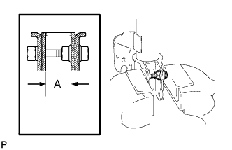
Standard length A 28 mm (1.10 in.)
-
-
INSTALL FRONT LOWER COIL SPRING INSULATOR
-
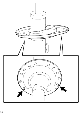
Install the front lower coil spring insulator to the front shock absorber assembly.
Text in Illustration 
Positioning Pin Note
Make sure that the positioning pins on the front lower coil spring insulator are inserted into the holes in the front shock absorber assembly.
-
-
INSTALL FRONT SPRING BUMPER
-
Install the front spring bumper to the front shock absorber assembly.
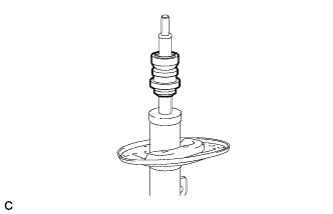
Note
Face the smaller diameter end of the front spring bumper downward.
-
-
INSTALL FRONT COIL SPRING
-
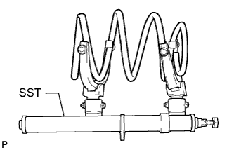
Install SST to the front coil spring with the hooks spread as far apart as possible from each other.
- SST
- 09727-30021 ( 09727-00010, 09727-00021, 09727-00031 )
Note
Make sure that the claws on the hooks are securely engaged to the spring.
If the front coil spring is compressed at an angle, using 2 SST will make the work easier.
-
Using SST, compress the front coil spring.
- SST
- 09727-30021 ( 09727-00010, 09727-00021, 09727-00031 )
Note
Do not use an impact wrench. It will damage SST.
-
Install the front coil spring to the front shock absorber assembly.
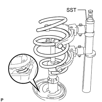
Note
Make sure that the end of the front coil spring is positioned in the depression of the front lower coil spring insulator.
-
-
INSTALL FRONT UPPER COIL SPRING INSULATOR
-
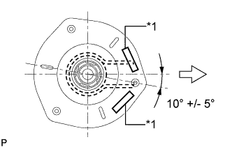
Install the front upper coil spring insulator as shown in the illustration.
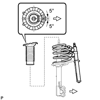
Text in Illustration 
Outside of the Vehicle Note
Any misalignment between the front shock absorber lower bracket and the alignment mark must be within +/- 5°.
-
-
INSTALL FRONT UPPER COIL SPRING SEAT
-
Install the front upper coil spring seat with the mark facing the outside of the vehicle.
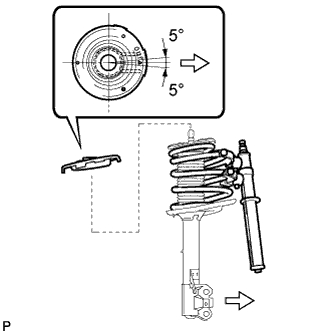
Text in Illustration Outside of the Vehicle Note
Any misalignment between the front shock absorber lower bracket and the alignment mark must be within +/- 5°.
-
-
INSTALL FRONT SUSPENSION SUPPORT BEARING
-
Install the front suspension support bearing as shown in the illustration.
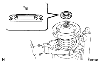
Text in Illustration *a Upper Side Note
Do not install the bearing upside down.
-
-
INSTALL FRONT SUSPENSION SUPPORT SUB-ASSEMBLY
-
Install the front suspension support sub-assembly as shown in the illustration.
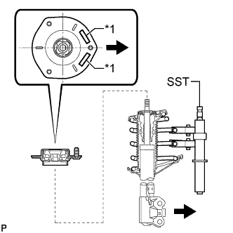
Text in Illustration *1 Rubber Foam Outside of the Vehicle Tech Tips
Check that the slot on the piston rod and the slot on the front suspension support sub-assembly are aligned.
-
Temporarily tighten a new front support to front shock absorber nut.
-
While aligning the stud bolt of the front suspension support sub-assembly and the front shock absorber lower bracket, remove SST from the front coil spring.
Text in Illustration *1 Rubber Foam Outside of the Vehicle Note
-
When reassembling the front suspension support sub-assembly, ensure that any misalignment between the absorber lower bracket and the stud bolt is within +/- 5°. Use the stud bolt that is closest to the outside of the vehicle.
-
Do not use an impact wrench. It will damage SST.
-
-
-
INSTALL FRONT SHOCK ABSORBER WITH COIL SPRING
-
Install the front shock absorber with coil spring (upper side) with the 3 nuts.
- Torque:
- 85 N*m { 867 kgf*cm, 63 ft.*lbf }
-
Install the front shock absorber with coil spring (lower side) to the steering knuckle and insert the 2 bolts and 2 nuts.
- Torque:
- 290 N*m { 2957 kgf*cm, 214 ft.*lbf }
Note
While keeping the bolts from rotating, tighten the nuts.
-
-
INSTALL FRONT STABILIZER LINK ASSEMBLY
-
Install the front stabilizer link assembly to the front shock absorber assembly with the nut.
- Torque:
- 125 N*m { 1275 kgf*cm, 92 ft.*lbf }
If the ball joint turns together with the nut, use a wrench to hold the stud bolt.
-
-
INSTALL FRONT SPEED SENSOR
-
Install the front speed sensor and front flexible hose to the front shock absorber assembly with the bolt and clamp.
- Torque:
- 19 N*m { 192 kgf*cm, 14 ft.*lbf }
Note
Do not twist the front speed sensor when installing it.
Tech Tips
Install the speed sensor harness bracket first and then the front flexible hose.
-
-
FULLY TIGHTEN FRONT SUPPORT TO FRONT SHOCK ABSORBER NUT
-
Fully tighten the front support to front shock absorber nut.
- Torque:
- 70 N*m { 714 kgf*cm, 52 ft.*lbf }
Note
Perform this step only when the front shock absorber with coil spring has been disassembled.
-
-
INSTALL FRONT WHEEL
- Torque:
- 103 N*m { 1049 kgf*cm, 76 ft.*lbf }
-
STABILIZE SUSPENSION
-
Lower the vehicle and bounce it up and down several times to stabilize the front suspension.
-
-
INSPECT AND ADJUST FRONT WHEEL ALIGNMENT