REAR STABILIZER BAR INSTALLATION

-
INSTALL REAR STABILIZER BUSHING (for LH Side)
-
Install the rear stabilizer bushing to the outside of the stopper ring on the rear stabilizer bar as shown in the illustration.
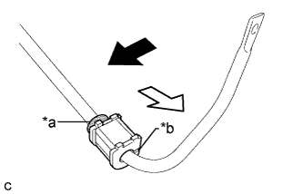
Text in Illustration *a Stopper Ring *b Cutout 
Front of the Vehicle 
Outside of the Vehicle Note
Install the rear stabilizer bushing so that the cutout face rearward.
-
-
INSTALL REAR STABILIZER BUSHING (for RH Side)
Tech Tips
Perform the same procedure as for the LH side.
-
INSTALL REAR NO. 1 STABILIZER BAR BRACKET (for LH Side)
-
Install the rear No. 1 stabilizer bar bracket to the rear stabilizer bar.
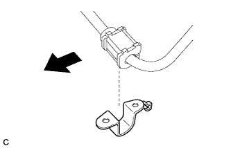
Text in Illustration Front of the Vehicle Note
Be sure to install the rear No. 1 stabilizer bar bracket in the correct direction.
-
-
INSTALL REAR NO. 1 STABILIZER BAR BRACKET (for RH Side)
Tech Tips
Perform the same procedure as for the LH side.
-
INSTALL REAR NO. 2 STABILIZER BAR BRACKET (for LH Side)
-
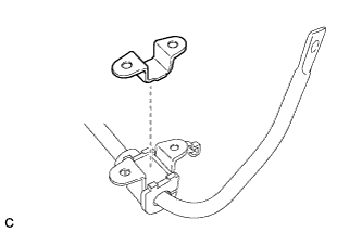
Install the rear No. 2 stabilizer bar bracket to the rear stabilizer bar.
-
-
INSTALL REAR NO. 2 STABILIZER BAR BRACKET (for RH Side)
Tech Tips
Perform the same procedure as for the LH side.
-
INSTALL REAR STABILIZER BAR
-
Install the rear stabilizer bar with the 4 bolts.
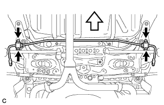
Text in Illustration Bolt Front of the Vehicle - Torque:
- 31 N*m { 316 kgf*cm, 23 ft.*lbf }
-
-
INSTALL REAR STABILIZER LINK ASSEMBLY LH
-
Install the rear stabilizer link assembly LH to the rear shock absorber with coil spring with the nut.
- Torque:
- 39 N*m { 400 kgf*cm, 29 ft.*lbf }
If the ball joint turns together with the nut, use a hexagon wrench to hold the stud.
-
Install the rear stabilizer link assembly LH to the rear stabilizer bar with the nut.
- Torque:
- 39 N*m { 400 kgf*cm, 29 ft.*lbf }
If the ball joint turns together with the nut, use a hexagon wrench to hold the stud.
-
-
INSTALL REAR STABILIZER LINK ASSEMBLY RH
Tech Tips
Perform the same procedure as for the LH side.
-
INSTALL NO. 2 FLOOR UNDER COVER (w/ Floor Under Cover)
-
Install the No. 2 floor under cover with the 2 bolts, 3 nuts and 2 clips.
- Torque:
- Bolt
- 12 N*m { 122 kgf*cm, 9 ft.*lbf }
- Nut
- 4.0 N*m { 41 kgf*cm, 35 in.*lbf }
-
-
INSTALL NO. 1 FLOOR UNDER COVER
-
Install the No. 1 floor under cover with the 2 bolts, 3 nuts and 2 clips.
- Torque:
- Bolt
- 12 N*m { 122 kgf*cm, 9 ft.*lbf }
- Nut
- 4.0 N*m { 41 kgf*cm, 35 in.*lbf }
-
-
INSTALL REAR WHEELS
- Torque:
- 103 N*m { 1049 kgf*cm, 76 ft.*lbf }