WATER PUMP INSTALLATION

-
INSTALL ENGINE WATER PUMP ASSEMBLY
-
Install a new gasket and the engine water pump assembly together with the water pump pulley with the 16 bolts.
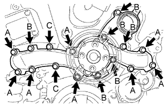
- Torque:
- Bolt A
- 21 N*m { 214 kgf*cm, 15 ft.*lbf }
- Bolt B and C
- 11 N*m { 112 kgf*cm, 8 ft.*lbf }
Note
-
Make sure that there is no oil on the threads of bolts A.
-
Be sure to replace 2 bolts C with new ones or reuse them after applying adhesive 1344.
Adhesive Toyota Genuine Adhesive 1344, Three Bond 1344 or equivalent
-
-
INSTALL WATER PUMP PULLEY
-
Temporarily install the water pump pulley with the 4 bolts.
-
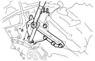
Using SST, hold the water pump pulley.
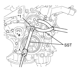
- SST
- 09960-10010 ( 09962-01000, 09963-00700 )
Text in Illustration *1 Union Nut Wrench *a 170 mm -
Using SST and union nut wrench, tighten the 4 bolts.
- SST
- 09961-00950
- Torque:
- without SST
- 21 N*m { 214 kgf*cm, 15 ft.*lbf }
- with SST
- 11 N*m { 112 kgf*cm, 8 ft.*lbf }
Note
-
The "with SST" torque value is effective when using SST with a fulcrum length of 170 mm (6.69 in.) and a torque wrench with a fulcrum length of 180 mm (7.09 in.) Click here.
-
The "with SST" torque value is effective when SST is parallel to the torque wrench.
-
-
INSTALL WATER INLET HOUSING
-
Install 2 new O-rings.
-
Install the water inlet housing with the 2 bolts and nut.
- Torque:
- 10 N*m { 102 kgf*cm, 7 ft.*lbf }
Note
Be careful not to allow the O-ring to get caught between the parts.
-
Connect the water hose.
-
-
INSTALL V-RIBBED BELT TENSIONER PULLEY
-
Install the V-ribbed belt tensioner pulley and dust shield with the bolt.
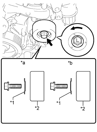
Text in Illustration *1 Dust Shield *2 Pulley *a Correct *b Incorrect Note
-
Be careful when tightening the bolt because its thread is left-handed.
-
Install the dust shield in the direction shown in the illustration. Failure to do so may cause looseness.
-
Make sure to use the removed bolt. (Do not use another bolt even if it is the same size.)
- Torque:
- 48 N*m { 489 kgf*cm, 35 ft.*lbf }
-
-
Install the 5 mm bi-hexagon wrench.
-
-
INSTALL NO. 2 IDLER PULLEY SUB-ASSEMBLY
-
Install the idler pulley cover plate, No. 2 idler pulley sub-assembly and No. 2 idler pulley cover plate with the bolt.
- Torque:
- 54 N*m { 550 kgf*cm, 40 ft.*lbf }
-
-
INSTALL FRONT NO. 1 ENGINE MOUNTING BRACKET LH
-
Temporarily install the front No. 1 engine mounting bracket LH with the 6 bolts.
-
Fully tighten the 5 bolts.
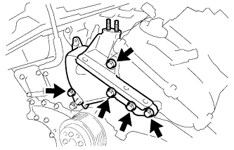
- Torque:
- 54 N*m { 551 kgf*cm, 40 ft.*lbf }
-
Using SST, fully tighten the bolt.
- SST
- 09961-00950
Text in Illustration *a 150 mm - Torque:
- without SST
- 54 N*m { 551 kgf*cm, 40 ft.*lbf }
- with SST
- 34 N*m { 347 kgf*cm, 25 ft.*lbf }
Note
-
The "with SST" torque value is effective when using SST with a fulcrum length of 150 mm (5.905 in.) and a torque wrench with a fulcrum length of 260 mm (10.23 in.) Click here.
-
The "with SST" torque value is effective when SST is parallel to the torque wrench.
-
-
INSTALL ENGINE MOVING CONTROL ROD BRACKET
-
When replacing the engine moving control rod.
-
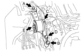
Install the engine moving control rod bracket with engine moving control rod with the 4 bolts.
- Torque:
- 38 N*m { 387 kgf*cm, 28 ft.*lbf }
Note
Temporarily tighten bolt A and B, and then fully tighten the 4 bolts in the order of C, D, A and B.
-
Tighten the bolt E.
- Torque:
- 52 N*m { 530 kgf*cm, 38 ft.*lbf }
-
-
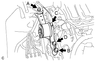
When not replacing the engine moving control rod.
-
Install the engine moving control rod bracket with engine moving control rod with the 4 bolts.
- Torque:
- 38 N*m { 387 kgf*cm, 28 ft.*lbf }
Note
Temporarily tighten bolt A and B, and then fully tighten the 4 bolts in the order of C, D, A and B.
-
-
-
INSTALL NO. 2 ENGINE MOUNTING STAY RH (for Intake Manifold Side)
-
Install the No. 2 engine mounting stay RH with the bolt.
- Torque:
- 21 N*m { 214 kgf*cm, 15 ft.*lbf }
-
-
INSTALL NO. 2 ENGINE MOUNTING STAY RH (for Engine Mounting stay Side)
-
Install the No. 2 engine mounting stay RH with the bolt.
- Torque:
- 38 N*m { 387 kgf*cm, 28 ft.*lbf }
-
Tighten the 2 nuts.
- Torque:
- 23 N*m { 234 kgf*cm, 17 ft.*lbf }
-
-
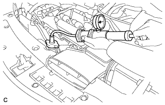
CONNECT OUTLET RADIATOR HOSE
-
Connect the outlet radiator hose with the hose clip.
-
-
INSTALL V-RIBBED BELT
-
ADD ENGINE COOLANT
-
Tighten the radiator drain cock plug by hand.
-
Close the 2 cylinder block drain cock plugs.
- Torque:
- 13 N*m { 130 kgf*cm, 9 ft.*lbf }
-
Loosen the air drain cock plug on the water inlet housing.
-
Add TOYOTA Super Long Life Coolant (SLLC) to the radiator inlet opening until coolant overflows from the air drain cock hole. Then tighten the air drain cock plug to the water inlet housing.
- Torque:
- 13 N*m { 130 kgf*cm, 9 ft.*lbf }
-
Slowly fill the radiator with TOYOTA Super Long Life Coolant (SLLC).
Specified capacity 9.1 liters (9.6 US qts, 8.0 lmp. qts) Tech Tips
TOYOTA vehicles are filled with TOYOTA SLLC at the factory. In order to avoid damage to the engine cooling system and other technical problems, only use TOYOTA SLLC or similar high quality ethylene glycol based non-silicate, non-amine, non-nitrite, non-borate coolant with long-life hybrid organic acid technology (coolant with long-life hybrid organic acid technology is a combination of low phosphates and organic acids).
-
Slowly pour coolant into the radiator reserve tank assembly until it reaches the full line.
-
Squeeze the inlet and outlet radiator hoses several times by hand, and then check the level of the coolant.
If the coolant level is low, add coolant.
-
Install the radiator cap sub-assembly and reserve tank cap.
-
Bleed air from the cooling system.
Note
-
Before starting the engine, turn the A/C switch off.
-
Adjust the heater control to the maximum hot setting.
-
Adjust the blower speed to the low setting.
-
Warm up the engine until the thermostat opens. While the thermostat is open, circulate the coolant for several minutes.
Tech Tips
The thermostat open timing can be confirmed by squeezing the outlet radiator hose by hand, and sensing vibrations when the engine coolant starts to flow inside the hose.
-
Maintain the engine speed at 2500 to 3000 rpm.
-
Squeeze the inlet and outlet radiator hoses several times by hand to bleed air.
CAUTION:
When squeezing the radiator hoses:
-
Wear protective gloves.
-
Be careful as the radiator hoses are hot.
-
Keep your hands away from the radiator fans.
Note
-
Make sure that the radiator reserve tank assembly still has some coolant in it.
-
If the coolant temperature gauge indicates an excessive temperature, turn off the engine and let it cool.
-
If there is not enough coolant, the engine may overheat or be seriously damaged.
-
If the radiator reserve tank assembly does not have enough coolant, perform the following: 1) stop the engine, 2) wait until the coolant has cooled down, and 3) add coolant until the reserve tank assembly is filled to the full line.
-
-
-
Stop the engine, and wait until the engine coolant cools down.
-
Add engine coolant to the full line on the radiator reserve tank assembly.
-
-
INSPECT FOR COOLANT LEAK
CAUTION:
Do not remove the radiator cap sub-assembly while the engine and radiator are still hot. Pressurized, hot engine coolant and steam may be released and cause serious burns.
Note
Before performing each inspection, turn the A/C switch OFF.
-
Fill the radiator with coolant and attach a radiator cap tester.
-
Warm up the engine.
-
Using a radiator cap tester, increase the pressure inside the radiator to 118 kPa (1.2 kgf*cm, 17 psi), and check that the pressure does not drop.
If the pressure drops, check the hoses, radiator and water pump for leaks. If no external leaks are found, check the heater core, cylinder block and cylinder head.
-