STARTER INSPECTION

-
INSPECT STARTER ASSEMBLY
CAUTION:
As a large electric current passes through the cable during this inspection, a thick cable must be used. If not, the cable may became hot and cause injury.
Note
These tests must be performed within 3 to 5 seconds to avoid burning out the coil.
-
Perform a pull-in test.
-
Remove the nut and disconnect the lead wire from terminal C.
-
Connect the battery to the magnetic switch as shown in the illustration. Check that the clutch pinion gear extends.
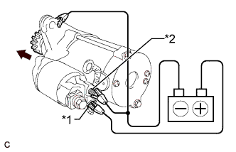
Text in Illustration *1 Terminal 50 *2 Terminal C If the clutch pinion gear does not move, replace the magnetic switch assembly.
-
-
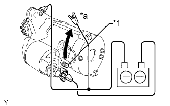
Perform a hold-in test.
-
While maintaining the battery connections of the pull-in test above, disconnect the negative (-) lead from terminal C. Check that the pinion gear remains extended.
Text in Illustration *1 Terminal C *a Disconnect If the clutch pinion gear returns inward, replace the magnetic switch assembly.
-
-
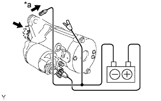
Perform a clutch pinion gear return test.
-
Disconnect the negative (-) lead from the starter body. Check that the clutch pinion gear returns.
If the clutch pinion gear does not return, replace the magnetic switch assembly.
Text in Illustration *a Disconnect
-
-
Perform a no-load performance test.
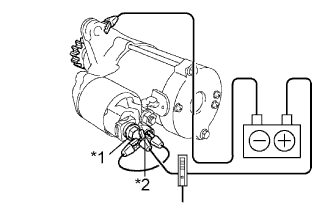
Text in Illustration *1 Terminal 30 *2 Terminal 50 -
Connect the lead wire to terminal C with the nut. Make sure that the lead is not grounded.
- Torque:
- 10 N*m { 102 kgf*cm, 7 ft.*lbf }
-
Clamp the starter in a vise.
-
Connect the battery and an ammeter to the starter as shown in the illustration.
-
Check that the starter rotates smoothly and steadily while the pinion gear is moving out. Then measure the current.
Standard current 90 A or less at 11.5 V If the result is not as specified, repair or replace the starter assembly.
-
-
-
INSPECT REPAIR SERVICE STARTER KIT
-
Check the plunger.
-
Push in the plunger and check that it returns quickly to its original position.
If necessary, replace the repair service starter kit.
-
-
Check if the pull-in coil has an open circuit.
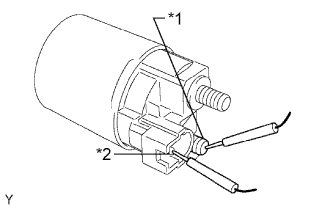
Text in Illustration *1 Terminal C *2 Terminal 50 -
Measure the resistance between terminals 50 and C.
Standard resistance Below 1 Ω If the result is not as specified, replace the repair service starter kit.
-
-
Check if the hold-in coil has an open circuit.
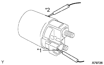
Text in Illustration *1 Terminal 50 *2 Body -
Measure the resistance between terminal 50 and the switch body.
Standard resistance Below 2 Ω If the result is not as specified, replace the repair service starter kit.
-
-
-
INSPECT STARTER ARMATURE ASSEMBLY
Tech Tips
If these is no continuity between any segments, replace the starter armature assembly.
-
Check the commutator for contamination and burns on its surface.
If the surface is dirty or burnt, correct it with sandpaper (No. 400) or a lathe.
-
Check if the commutator has an open circuit.

Text in Illustration *1 Segment -
Measure the resistance between the segments of the commutator.
Standard resistance Below 1 Ω If the result is not as specified, replace the armature assembly.
-
-
Check if the commutator is grounded.
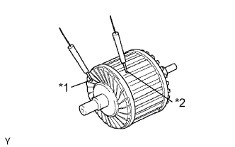
Text in Illustration *1 Commutator *2 Coil Core -
Measure the resistance between the commutator and armature coil core.
Standard resistance 10 kΩ or higher If the result is not as specified, replace the armature assembly.
-
-
Using a vernier caliper, measure the commutator length.
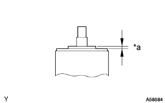
Text in Illustration *a Length Standard length 3.1 to 3.8 mm (0.122 to 0.149 in.) Maximum length 3.8 mm (0.149 in.) If the length is greater than the maximum, replace the starter armature assembly.
-
-
INSPECT STARTER COMMUTATOR END FRAME ASSEMBLY
-
Using a vernier caliper, measure the brush length.
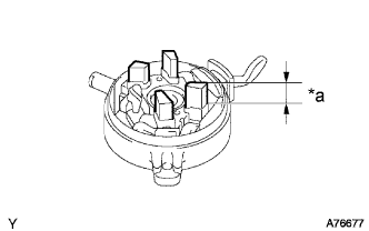
Text in Illustration *a Length Standard length 4.0 to 9.0 mm (0.158 to 0.354 in.) Minimum length 4.0 mm (0.158 in.) If the length is less than the minimum, replace the end frame assembly.
-
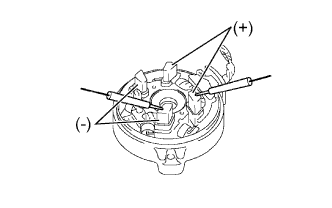
Check the brush insulation.
-
Measure the resistance between the positive (+) and negative (-) brushes.
Standard resistance 10 kΩ or higher If the result is not as specified, replace the end frame assembly.
-
-
-
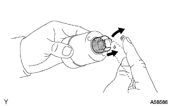
INSPECT STARTER CLUTCH
-
Rotate the clutch pinion gear counterclockwise and check that it turns freely. Try to rotate the clutch pinion gear clockwise and check that it locks.
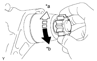
Text in Illustration *a Lock *b Free If necessary, replace the starter drive housing assembly.
-