FUEL PUMP INSTALLATION

-
INSTALL FUEL SUCTION TUBE WITH PUMP AND GAUGE ASSEMBLY
-
Install a new fuel suction tube set gasket to the fuel suction tube.
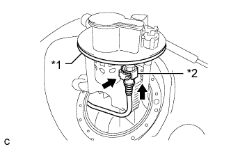
Text in Illustration *1 Fuel Suction Tube Set Gasket *2 Fuel Cut-off Tube -
Push in the fuel cut-off tube connector to the fuel suction tube assembly and push the retainer so that the claws engage.
-
Install the fuel suction tube with pump and gauge assembly to the fuel tank.
Note
Be careful that the arm of the sender gauge does not bend.
-
-
INSTALL FUEL TANK VENT TUBE SET PLATE
-
Align the protrusion of the fuel suction tube assembly and the cutout of the fuel tank vent tube set plate.
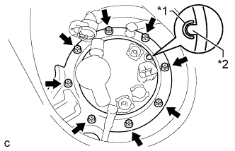
Text in Illustration *1 Cutout *2 Protrusion -
Install the set plate with the 8 bolts.
- Torque:
- 6.0 N*m { 61 kgf*cm, 53 in.*lbf }
-
-
CONNECT FUEL TANK MAIN TUBE SUB-ASSEMBLY
-
Push the fuel tube joint in the plug of the fuel suction plate, then install the tube joint clip.
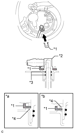
Text in Illustration *1 Tube Joint Clip *2 Fuel Tube Joint *3 O-ring *4 Collar *a CORRECT *b INCORRECT Note
-
Check that there are no scratches or foreign matter around the connected part of the fuel tube joint and plug before performing this work.
-
Check that the fuel tube joint is securely inserted to the end.
-
Check that the tube joint clip is on the collar of the fuel tube joint.
-
After installing the tube joint clip, check that the fuel tank main tube cannot be pulled out.
-
-
-
CONNECT FUEL TANK BREATHER ELBOW TUBE SUB-ASSEMBLY
-
Push the fuel tube joint in the plug of the fuel suction plate, then install the tube joint clip.
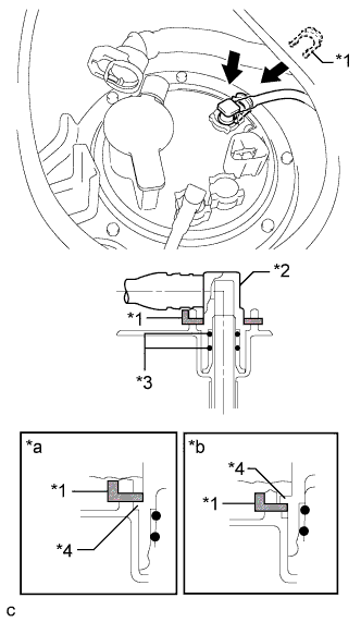
Text in Illustration *1 Tube Joint Clip *2 Fuel Tube Joint *3 O-ring *4 Collar *a CORRECT *b INCORRECT Note
-
Check that there are no scratches or foreign matter around the connected part of the fuel tube joint and plug before performing this work.
-
Check that the fuel tube joint is securely inserted to the end.
-
Check that the tube joint clip is on the collar of the fuel tube joint.
-
After installing the tube joint clip, check that the fuel tube joint cannot be pulled out.
-
-
-
CONNECT FUEL TANK VENT HOSE
-
Push in the fuel tank vent hose connector to the fuel suction tube assembly and push the retainer so that the claws engage.
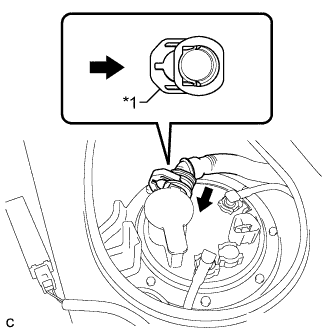
Text in Illustration *1 Retainer Note
-
Check that there are no scratches or foreign matter around the connected parts of the fuel tank vent hose connector and fuel suction tube assembly before performing this work.
-
After connecting the fuel tank vent hose sub-assembly, check that the fuel tank vent hose sub-assembly is securely connected by pulling on the fuel tank vent hose connector.
-
-
Connect the fuel pump connector.
-
-
CONNECT CABLE TO NEGATIVE BATTERY TERMINAL
Note
When disconnecting the cable, some systems need to be initialized after the cable is reconnected Click here.
-
INSTALL REAR FLOOR SERVICE HOLE COVER
-
Install the rear floor service hole cover with new butyl tape.
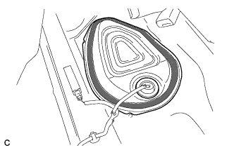
Text in Illustration 
Butyl Tape
-
-
INSPECT FOR FUEL LEAK
-
Check fuel pump operation.
-
Connect the Techstream to the DLC3.
-
Turn the engine switch on (IG) and turn the Techstream on.
Note
Do not start the engine.
-
Enter the following menus: Powertrain / Engine / Active Test / Control the Fuel Pump / Speed.
-
Check for pressure in the fuel inlet tube from the fuel line. Check that sounds of fuel flowing from the fuel tank can be heard. If no sounds can be heard, check the integration relay, fuel pump, fuel pump control ECU, ECM and wiring connectors.
-
-
Inspect for fuel leaks.
-
Check that there are no fuel leaks from the fuel system after doing any maintenance or repairs. If there is a fuel leak, repair or replace parts as necessary.
-
-
Turn the engine switch off.
-
Disconnect the Techstream from the DLC3.
-
-
INSTALL REAR SEAT CUSHION LOCK HOOK
-
Engage the claw to install a new rear seat cushion lock hook.
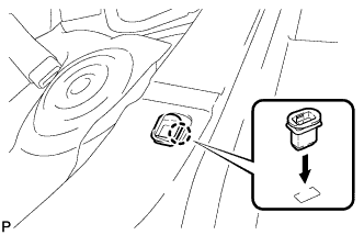
Note
Rear seat cushion lock hooks must not be reused.
Tech Tips
Use the same procedure for the RH side and the LH side.
-
-
INSTALL REAR SEAT CUSHION ASSEMBLY
-
Place the rear seat cushion assembly in the cabin.
Note
Be careful not to damage the vehicle body.
-
Engage the 2 hooks of the seat cushion to the vehicle body as shown in the illustration.
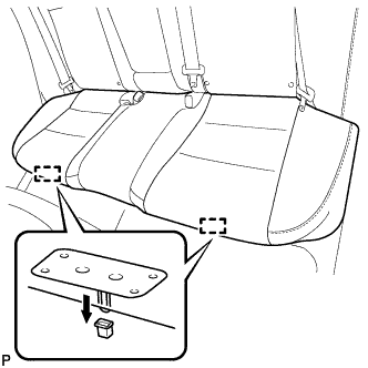
-
Confirm that the seat cushion is firmly installed.
Note
When installing the seat cushion, make sure that the seat belt buckles are not under the seat cushion.
-