AUTOMATIC TRANSAXLE SYSTEM, Diagnostic DTC:P2769, P2770

| DTC Code | DTC Name |
|---|---|
| P2769 | Short in Torque Converter Clutch Solenoid Circuit (Shift Solenoid Valve SL) |
| P2770 | Open in Torque Converter Clutch Solenoid Circuit (Shift Solenoid Valve SL) |
DESCRIPTION
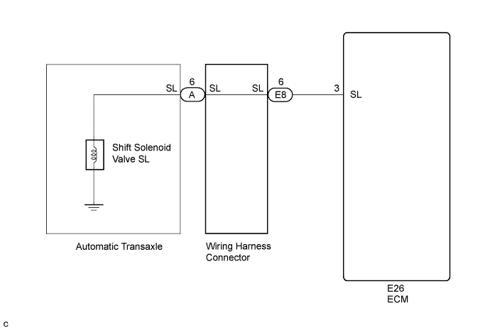
Shift solenoid valve SL is turned on and off by signals from the ECM to control the hydraulic pressure acting on the lock-up relay valve, which then controls operation of the lock-up clutch.
| DTC No. | DTC Detection Condition | Trouble Area |
|---|---|---|
| P2769 | ECM detects a short in the shift solenoid valve SL circuit when the shift solenoid valve SL is operated (2 trip detection logic). |
|
| P2770 | ECM detects an open in the shift solenoid valve SL circuit when the shift solenoid valve SL is not operated (2 trip detection logic). |
|
Fail-safe function:
If the ECM detects a malfunction, it turns shift solenoid valve SL off.
MONITOR DESCRIPTION
Based on the signals from the throttle position sensor, the air flow meter and the crankshaft position sensor, the ECM sends a signal to shift solenoid valve SL to regulate the hydraulic pressure and provide smoother torque converter clutch engagement. Shift solenoid valve SL responds to commands from the ECM. The valve controls the lock-up relay valve to perform the torque-converter lock-up function. If the ECM detects an open or short circuit for shift solenoid valve SL, it will illuminate the MIL.
MONITOR STRATEGY
| Related DTCs | P2769: Shift solenoid valve SL/Range check (Low resistance) P2770: Shift solenoid valve SL/Range check (High resistance) |
| Required sensors/Components | Shift solenoid valve SL |
| Frequency of operation | Continuous |
| Duration | 1 time |
| MIL operation | 2 driving cycles |
| Sequence of operation | None |
TYPICAL ENABLING CONDITIONS
| The monitor will run whenever the following DTCs are not present | None |
| Solenoid | ON |
| Time after solenoid OFF to ON | More than 0.008 sec. |
| The monitor will run whenever the following DTCs are not present | None |
| Solenoid | ON |
| Time after solenoid ON to OFF | More than 0.008 sec. |
TYPICAL MALFUNCTION THRESHOLDS
| Intelligent power MOS diagnosis fail signals detected while the solenoid is operated | Fail at solenoid resistance: 8 Ω or less |
| Intelligent power MOS diagnosis fail signals detected while the solenoid is not operated | Fail at solenoid resistance: 100 kΩ or more |
COMPONENT OPERATING RANGE
| Shift solenoid valve SL | Resistance: 11 to 15 Ω at 20°C (68°F) |
WIRING DIAGRAM
INSPECTION PROCEDURE
Note
Perform the universal trip to clear permanent DTCs Click here.
PROCEDURE
-
CHECK HARNESS AND CONNECTOR (SHIFT SOLENOID VALVE SL CIRCUIT)
-
Disconnect the ECM connector.
-
Measure the resistance according to the value(s) in the table below.
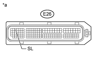
Standard Resistance Tester Connection Condition Specified Condition E26-3 (SL) - Body ground 20°C (68°F) 11 to 15 Ω Text in Illustration *a Front view of wire harness connector
(to ECM)
Result Result Proceed to OK A NG B
B 
CHECK HARNESS AND CONNECTOR (ECM - WIRING HARNESS CONNECTOR) Click here
A 
REPLACE ECM Click here
-
-
CHECK HARNESS AND CONNECTOR (ECM - WIRING HARNESS CONNECTOR)
-
Disconnect the harness connector from the wiring harness connector.
-
Measure the resistance according to the value(s) in the table below.
Standard Resistance Tester Connection Condition Specified Condition E26-3 (SL) - E8-6 (SL) Always Below 1 Ω E26-3 (SL) - Body ground and other terminals Always 10 kΩ or higher E8-6 (SL) - Body ground and other terminals Always 10 kΩ or higher
NG 
REPAIR OR REPLACE HARNESS OR CONNECTOR
OK 
-
-
INSPECT TRANSMISSION WIRE (SHIFT SOLENOID VALVE SL)
-
Remove the wiring harness connector from the transaxle.
-
Measure the resistance according to the value(s) in the table below.
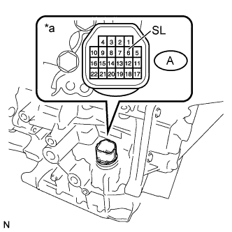
Standard Resistance Tester Connection Condition Specified Condition A-6 (SL) - Body ground 20°C (68°F) 11 to 15 Ω Text in Illustration *a Component without harness connected
(Transmission Wire)
NG
INSPECT SHIFT SOLENOID VALVE SL Click here
OK
REPLACE WIRING HARNESS CONNECTOR Click here
-
-
INSPECT SHIFT SOLENOID VALVE SL
-
Remove shift solenoid valve SL.
-
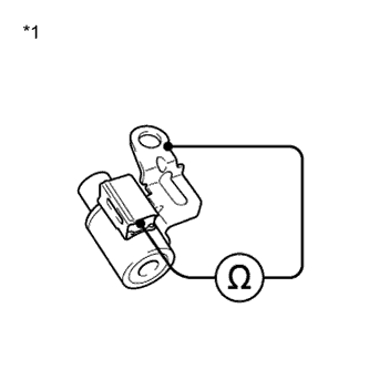
Measure the resistance according to the value(s) in the table below.
Standard Resistance Tester Connection Condition Specified Condition Solenoid Connector (SL) - Solenoid Body (SL) 20°C (68°F) 11 to 15 Ω Text in Illustration *1 Shift Solenoid Valve SL
NG
REPLACE SHIFT SOLENOID VALVE SL Click here
OK
REPLACE TRANSMISSION WIRE Click here
-