AUTOMATIC TRANSAXLE ASSEMBLY INSTALLATION

-
INSTALL TORQUE CONVERTER ASSEMBLY
-
Engage the splines of the input shaft and turbine runner.
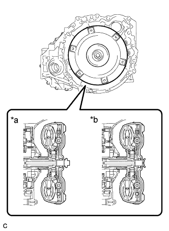
Text in Illustration *a Transaxle serial number 2########## *b Transaxle serial number 3########## -
Engage the splines of the stator shaft and the stator while turning the torque converter assembly.
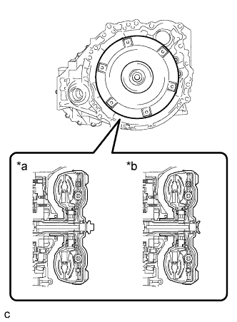
Text in Illustration *a Transaxle serial number 2########## *b Transaxle serial number 3########## Tech Tips
If the stator shaft splines are difficult to engage with the stator splines, move the torque converter back approximately 10 mm (0.393 in.) and engage the splines while rotating the torque converter.
-
Turn the torque converter assembly to insert the key of the oil pump drive gear into the groove of the torque converter assembly.
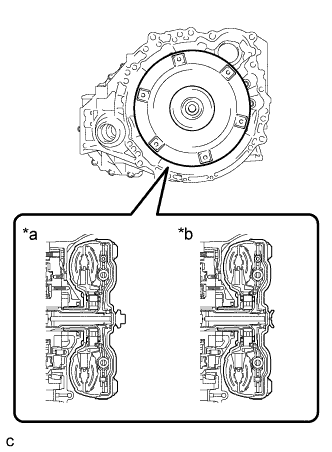
Text in Illustration *a Transaxle serial number 2########## *b Transaxle serial number 3########## -
Clean the torque converter set bolt holes.
-
Using a vernier caliper and straightedge, measure dimension A between the transaxle contact surface of the engine and the torque converter contact surface of the drive plate.
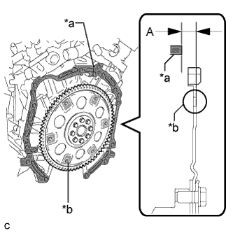
Text in Illustration *a Engine Surface *b Drive Plate Surface Note
Make sure to deduct the thickness of the straightedge.
-
Using a vernier caliper and straightedge, measure dimension B shown in the illustration and check that dimension B is more than dimension A, which was measured in the previous step.
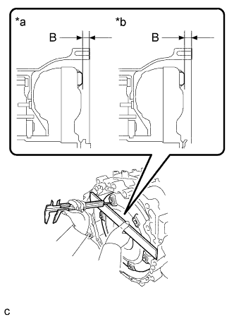
Text in Illustration *a Transaxle serial number 2########## *b Transaxle serial number 3########## Standard A + 1 mm (0.0394 in.) or more Note
-
Make sure to deduct the thickness of the straightedge.
-
If the transaxle is installed to the engine with the torque converter not sufficiently inserted, the torque converter may be damaged.
-
-
-
INSTALL SPEEDOMETER DRIVEN HOLE (ATM) COVER SUB-ASSEMBLY
-
Apply ATF to a new O-ring and install it to the speedometer driven hole (ATM) cover sub-assembly.
-
Install the speedometer driven hole (ATM) cover sub-assembly to the automatic transaxle assembly with the bolt.
- Torque:
- 5.5 N*m { 56 kgf*cm, 49 in.*lbf }
-
-
INSTALL NO. 1 TRANSMISSION CONTROL CABLE BRACKET
-
Install the No. 1 transmission control cable bracket to the automatic transaxle assembly with the 2 bolts.
- Torque:
- 12 N*m { 122 kgf*cm, 9 ft.*lbf }
-
-
INSTALL WIRE HARNESS CLAMP BRACKET
-
Install the 5 wire harness clamp brackets to the automatic transaxle assembly with the 5 bolts.
- Torque:
- 8.0 N*m { 82 kgf*cm, 71 in.*lbf }
-
-
INSTALL FRONT ENGINE MOUNTING BRACKET
-
Install the front engine mounting bracket with the 3 bolts.
- Torque:
- 64 N*m { 652 kgf*cm, 47 ft.*lbf }
-
-
INSTALL AUTOMATIC TRANSAXLE ASSEMBLY
-
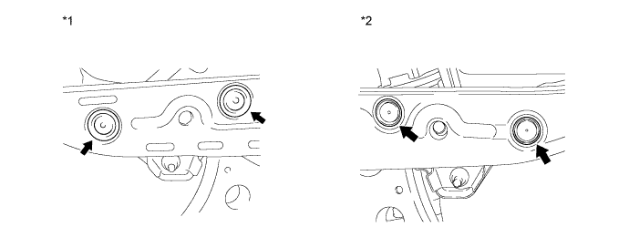
Apply clutch spline grease to the surface of the crankshaft that contacts the torque converter centerpiece.
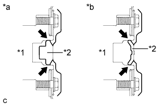
Text in Illustration *1 Crankshaft *2 Torque Converter Centerpiece *a Transaxle serial number 2########## *b Transaxle serial number 3########## Clutch spline grease Toyota Genuine Clutch Spline Grease or equivalent Maximum grease amount Approximately 1 g (0.0353 oz.) -
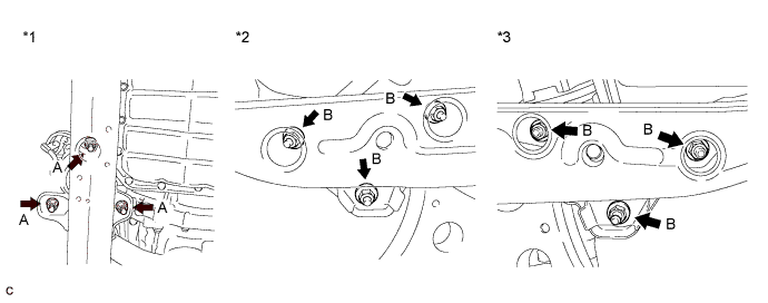
While keeping the engine and automatic transaxle assembly horizontal, align the knock pins with the holes in the automatic transaxle assembly and install the 10 bolts shown in the illustration.
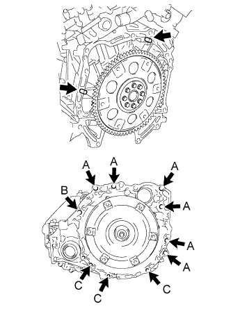
- Torque:
- Bolt A
- 64 N*m { 653 kgf*cm, 47 ft.*lbf }
- Bolt B
- 64 N*m { 653 kgf*cm, 47 ft.*lbf }
- Bolt C
- 43 N*m { 438 kgf*cm, 32 ft.*lbf }
Note
-
Confirm that the 2 knock pins are installed to the transaxle contact surface of the engine cylinder block before installing the transaxle.
-
Do not forcibly pry on the automatic transaxle assembly.
-
Check that the torque converter rotates.
Tech Tips
Bolt length:
-
Bolt A: 55 mm (2.17 in.)
-
Bolt B: 50 mm (1.97 in.)
-
Bolt C: 33 mm (1.30 in.)
-
Clean and degrease the bolt and the installation hole in the automatic transaxle.
-
Apply a few drops of adhesive to 2 or 3 threads at the tip of each of the bolt.
Adhesive Toyota Genuine Adhesive 1344, Three Bond 1344 or equivalent -
Install the bolt.
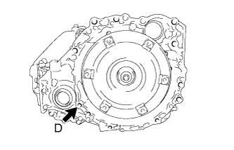
- Torque:
- Bolt D
- 46 N*m { 469 kgf*cm, 34 ft.*lbf }
Tech Tips
Bolt length:
-
Bolt D: 41 mm (1.61 in.)
-
-
INSTALL WIRE HARNESS
-
Connect the 7 clamps and connector.
-
Install the wire harnesses with the bolt.
- Torque:
- 12 N*m { 122 kgf*cm, 9 ft.*lbf }
-
-
INSTALL TRANSMISSION OIL COOLER
-
Install the transmission oil cooler with the transmission oil cooler stay to the automatic transaxle assembly with the 2 bolts.
- Torque:
- 14 N*m { 138 kgf*cm, 10 ft.*lbf }
-
Install the No. 1 oil cooler outlet hose and No. 1 oil cooler inlet hose.
-
Install the No. 4 water by-pass hose.
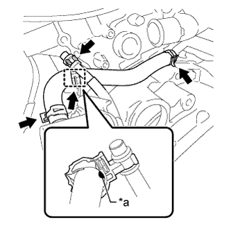
Text in Illustration *a Paint Note
-
Install the clamp so that the neck of the clamp is aligned with the paint.
-
Ensure that the paint is completely covered by the clamp.
-
-
Install the clamp and connect the breather plug.
-
-
INSTALL TCM
-
Install the TCM to the automatic transaxle assembly.
-
Install and tighten the 2 bolts in the order shown in the illustration.
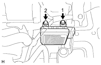
- Torque:
- 11 N*m { 115 kgf*cm, 8 ft.*lbf }
-
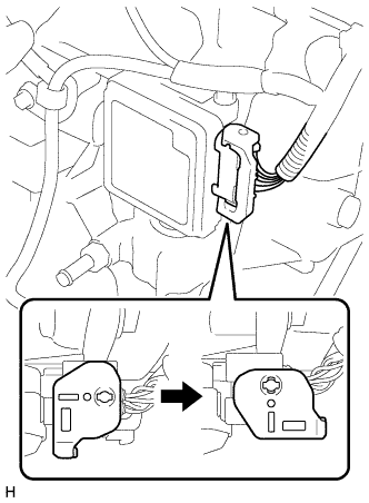
Connect the connector to the TCM.
-
Turn the lock lever and secure the connector with the lock lever.
-
-
INSTALL FRONT FRAME ASSEMBLY
-
Install the engine mounting insulator RH with the nut.
- Torque:
- 95 N*m { 969 kgf*cm, 70 ft.*lbf }
-
Install the engine mounting insulator LH with the nut.
- Torque:
- 95 N*m { 969 kgf*cm, 70 ft.*lbf }
-
Install the front engine mounting insulator assembly with the bolt.
- Torque:
- 87 N*m { 888 kgf*cm, 65 ft.*lbf }
-
Connect the 2 wire clamps and vacuum switching valve connector.
-
Connect the 2 wire clamps and oil pressure switch connector.
-
Fully tighten the 9 temporarily installed nuts of the engine mounting insulators to the specified torque.
Tech Tips
Perform this procedure only when replacement of the engine mounting insulator is necessary.
Text in Illustration *1 Front Engine Mounting Insulator Assembly *2 Engine Mounting Insulator RH *3 Engine Mounting Insulator LH - - - Torque:
- A
- 52 N*m { 530 kgf*cm, 38 ft.*lbf }
- Torque:
- B
- 87 N*m { 887 kgf*cm, 64 ft.*lbf }
-
Install the 4 hole plugs.
Tech Tips
Perform this procedure only when replacement of the engine mounting insulator is necessary.
Text in Illustration *1 Engine Mounting Insulator RH *2 Engine Mounting Insulator LH
-
-
INSTALL ENGINE ASSEMBLY WITH TRANSAXLE
-
CHECK AUTOMATIC TRANSAXLE SYSTEM
Note
If automatic transmission parts have been replaced, refer to Parts Replacement Compensation Table to determine if any additional operations are necessary Click here.