- Click here
REMOVE V-BANK COVER SUB-ASSEMBLY
-
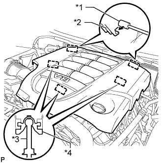
Поднимите переднюю часть декоративной крышки V-образного двигателя, чтобы открепить 3 штифта. Затем снимите 2 крюка декоративной крышки V-образного двигателя с кронштейна, чтобы снять декоративную крышку V-образного двигателя.
Table 1. Обозначения на рисунке *1 Кронштейн *2 Крепежный крюк *3 Штифт *4 Уплотнительная шайба
-
- Click here
INSPECT VACUUM SWITCHING VALVE ASSEMBLY (for ACIS)
-
Disconnect the vacuum switching valve connector.
-
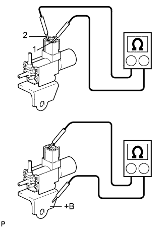
Measure the resistance according to the value(s) in the table below.
Table 2. Text in Illustration *a Body Ground Standard Resistance Tester Connection Condition Specified Condition 1 - 2 20°C (68°F) 37 to 44 Ω 1 - Body ground Always 1 MΩ or higher 2 - Body ground If the result is not as specified, replace the vacuum switching valve assembly.
-
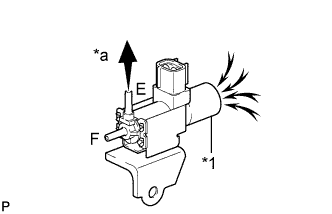
When applying vacuum to port E, check that air is sucked into the filter.
Table 3. Text in Illustration *1 Filter *a Vacuum If the result is not as specified, replace the vacuum switching valve assembly.
-
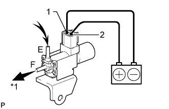
Apply battery voltage to the connector, and check the VSV operation.
OK Measurement Condition Specified Condition Battery positive (+) → Terminal 1
Battery negative (-) → Terminal 2
Air is sucked into port E when a vacuum is applied to port F Table 4. Text in Illustration *a Vacuum If the result is not as specified, replace the vacuum switching valve assembly.
-
Connect the vacuum switching valve connector.
-
- Click here
INSTALL V-BANK COVER SUB-ASSEMBLY
-

Совместите 2 крюка крышки V-образного двигателя с кронштейном. Затем совместите 3 уплотнительных шайбы декоративной крышки V-образного двигателя с 3 штифтами и нажмите на декоративную крышку V-образного двигателя, чтобы закрепить штифты.
Table 5. Обозначения на рисунке *1 Кронштейн *2 Крепежный крюк *3 Штифт *4 Уплотнительная шайба
-