УЗЕЛ ТОПЛИВНОГО БАКА УСТАНОВКА
-
INSTALL FUEL TANK TO FILLER PIPE HOSE
-
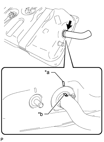
Install the hose to the fuel sub tank as shown in the illustration.
Text in Illustration *a Tank Side Mark *b Hose Side Mark Tech Tips
-
Align the fuel sub tank side mark with the hose side mark when installing the hose.
-
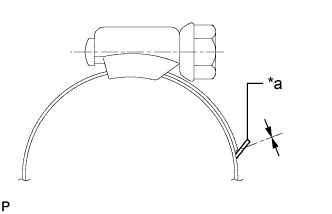
Tighten the hose clamp until the end of the hose clamp contacts the stopper as shown in the illustration.
Text in Illustration *a Stopper -
-
-
INSTALL NO. 3 FUEL HOSE
-
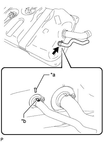
Install the fuel hose to the fuel sub tank as shown in the illustration.
Text in Illustration *a Tank Side Mark *b Hose Side Mark Tech Tips
-
Align the fuel sub tank side mark with the hose side mark when installing the hose.
-
Tighten the hose clamp until the end of the hose clamp contacts the stopper as shown in the illustration.
Text in Illustration *a Stopper -
-
-
INSTALL FUEL TANK BREATHER HOSE
-
Install the breather hose to the fuel sub tank.
-
-
INSTALL FUEL AND EVAPORATION VENT TUBE SUB-ASSEMBLY
-
Install a new gasket to the fuel and evaporation vent tube.
-
Install the fuel and evaporation vent tube with the 6 bolts.
- Torque:
- 3.5 N*m { 36 kgf*cm, 31 in.*lbf }
-
-
INSTALL FUEL TANK EVAPORATION VENT TUBE SUB-ASSEMBLY
-
except G.C.C. Countries:
Install the 2 fuel tank evaporation vent tubes.
-
for G.C.C. Countries:
Install the fuel tank evaporation vent tube.
-
-
INSTALL FUEL HOSE
-
Install the fuel hose.
-
-
INSTALL FUEL SENDER GAUGE ASSEMBLY
-
Install a new gasket to the sender gauge.
Note
Be careful not to bend the arm of the fuel sender gauge.
-
Install the sender gauge with the 5 screws.
- Torque:
- 1.5 N*m { 15 kgf*cm, 13 in.*lbf }
-
-
INSTALL FLOOR NO. 3 WIRE
-
Attach the wire harness clamp to the fuel sub tank.
-
Connect the sender gauge connector.
-
-
INSTALL FUEL SUB TANK SUB-ASSEMBLY
-
Set the fuel sub tank on a transmission jack and raise the fuel sub tank.
-
Connect the 2 fuel tank bands with the 2 bolts.
- Torque:
- 40 N*m { 408 kgf*cm, 30 ft.*lbf }
-
Connect the floor No. 3 wire connector.
-
Attach the 3 wire harness clamps.
-
-
CONNECT FUEL TANK TO FILLER PIPE HOSE
-
Connect the hose to the filler pipe.
-
-
CONNECT NO. 3 FUEL HOSE
-
Connect the fuel hose to the filler pipe.
-
-
CONNECT FUEL TANK BREATHER HOSE
-
Connect the breather hose to the filler pipe.
-
-
CONNECT FUEL HOSE
-
Connect the fuel hose.
-
-
CONNECT FUEL TANK EVAPORATION VENT TUBE SUB-ASSEMBLY
-
except G.C.C. Countries:
Connect the 2 fuel tank evaporation vent tubes.
-
for G.C.C. Countries:
Connect the fuel tank evaporation vent tube.
-
-
INSTALL FUEL TANK CAP ASSEMBLY
-
INSTALL NO. 1 SPARE WHEEL STOPPER
-
Install the spare wheel stopper with the 2 bolts.
- Torque:
- 32 N*m { 326 kgf*cm, 24 ft.*lbf }
-
-
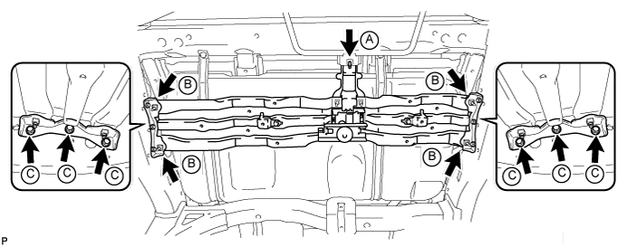
INSTALL SPARE WHEEL CARRIER CROSSMEMBER AND SPARE WHEEL CARRIER BRACKET
-
Install the spare wheel carrier crossmember and 2 brackets to the vehicle with the 6 bolts labeled C.
- Torque:
- for bolt C
- 20 N*m { 204 kgf*cm, 15 ft.*lbf }
-
Temporarily install the bolt labeled A, and then tighten the bolt labeled A and bolts labeled B.
- Torque:
- for bolt A
- 29 N*m { 296 kgf*cm, 21 ft.*lbf }
- for bolt B
- 20 N*m { 204 kgf*cm, 15 ft.*lbf }
-
-
INSTALL TAILPIPE ASSEMBLY
-
Install the tailpipe to the 2 exhaust pipe supports.
-
Install a new gasket to the center exhaust pipe.
-
Connect the tailpipe to the center exhaust pipe.
-
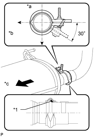
Text in Illustration *1 Gasket *a Top *b LH Side *c Front Attach a new clamp to the tailpipe and center exhaust pipe. Then install the bolt to the clamp.
- Torque:
- 32 N*m { 326 kgf*cm, 24 ft.*lbf }
Tech Tips
Install the clamp within the angle range shown in the illustration.
-
-
CONNECT CABLE TO NEGATIVE BATTERY TERMINAL
Note
When disconnecting the cable, some systems need to be initialized after the cable is reconnected Click here.
-
INSPECT FOR FUEL LEAK
-
Connect the intelligent tester to the DLC3.
-
Turn the engine switch on (IG) and intelligent tester main switch on.
Note
Do not start the engine.
-
Enter the following menus: Powertrain / Engine and ECT / Active Test / Control the Fuel Pump / Speed.
-
Check that there are no fuel leaks after doing maintenance anywhere on the fuel system.
-
-
INSPECT FOR EXHAUST GAS LEAK
При наличии утечки газа затяните соединения в местах утечки. При необходимости замените поврежденные детали.
-
INSTALL SPARE TIRE