РАСПРЕДВАЛ УСТАНОВКА
-
INSTALL CAMSHAFT BEARING CAP RH
-
Apply a light coat of engine oil to the camshaft journals, camshaft housings and bearing caps.
-
Install the No. 1 and No. 2 camshafts to the camshaft housing.
-
Confirm the marks and numbers on the camshaft bearing caps and place them in their proper positions and directions.
-
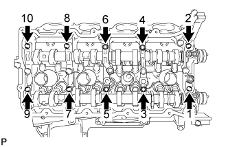
Temporarily install the 10 bolts in the order shown in the illustration.
-
-
INSTALL CAMSHAFT HOUSING SUB-ASSEMBLY RH
-
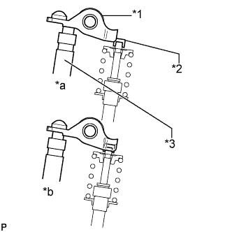
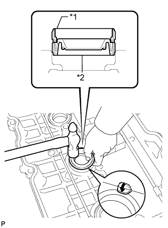
Text in Illustration *1 Valve Rocker Arm *2 Valve Stem Cap *3 Valve Lash Adjuster *a INCORRECT *b CORRECT Make sure that the valve rocker arms are installed as shown in the illustration.
-
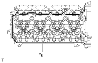
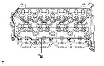
Text in Illustration *a 3.5 to 4.0 mm Apply seal packing in a continuous line as shown in the illustration.
Seal packing Toyota Genuine Seal Packing Black, Three Bond 1207B or equivalent Standard seal diameter 3.5 to 4.0 mm (0.138 to 0.157 in.) Note
-
Remove any oil from the contact surface.
-
Install the camshaft housing within 3 minutes and tighten the bolts within 15 minutes after applying seal packing.
-
-
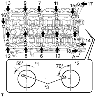
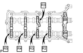
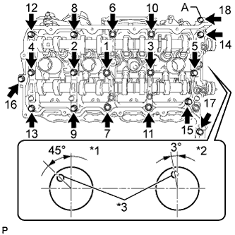
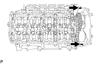
Text in Illustration *1 EX *2 IN *3 Knock Pin Install the camshaft housing, and install the 18 bolts in the order shown in the illustration.
- Torque:
- for bolt A
- 10 N*m { 102 kgf*cm, 7 ft.*lbf }
- except bolt A
- 30 N*m { 306 kgf*cm, 22 ft.*lbf }
Note
-
Do not start the engine for at least 2 hours after the installation.
-
Make sure that the knock pin of the camshaft is positioned as shown in the illustration before installing the camshaft housing.
-
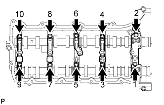
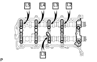
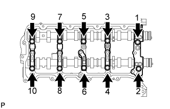
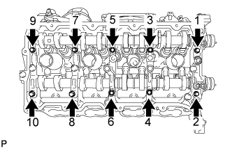
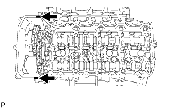
Tighten the 10 bolts in the order shown in the illustration.
- Torque:
- 16 N*m { 163 kgf*cm, 12 ft.*lbf }
Note
Thoroughly wipe clean any seal packing.
-
-
INSTALL CAMSHAFT BEARING CAP LH
-
Apply a light coat of engine oil to the camshaft journals, camshaft housings and bearing caps.
-
Install the No. 3 and No. 4 camshafts to the camshaft housing.
-
Confirm the marks and numbers on the camshaft bearing caps and place them in their proper positions and directions.
-
Temporarily install the 10 bolts in the order shown in the illustration.
-
-
INSTALL CAMSHAFT HOUSING SUB-ASSEMBLY LH
-
Text in Illustration *1 Valve Rocker Arm *2 Valve Stem Cap *3 Valve Lash Adjuster *a INCORRECT *b CORRECT Make sure that the valve rocker arms are installed as shown in the illustration.
-
Text in Illustration *a 3.5 to 4.0 mm Apply seal packing in a continuous line as shown in the illustration.
Seal packing Toyota Genuine Seal Packing Black, Three Bond 1207B or equivalent Standard seal diameter 3.5 to 4.0 mm (0.138 to 0.157 in.) Note
-
Remove any oil from the contact surface.
-
Install the camshaft housing within 3 minutes and tighten the bolts within 15 minutes after applying seal packing.
-
-
Text in Illustration *1 IN *2 EX *3 Knock Pin Install the camshaft housing, and install the 18 bolts in the order shown in the illustration.
- Torque:
- for bolt A
- 10 N*m { 102 kgf*cm, 7 ft.*lbf }
- except bolt A
- 30 N*m { 306 kgf*cm, 22 ft.*lbf }
Note
-
Do not start the engine for at least 2 hours after the installation.
-
Make sure that the knock pin of the camshaft is positioned as shown in the illustration before installing the camshaft housing.
-
Tighten the 10 bolts in the order shown in the illustration.
- Torque:
- 16 N*m { 163 kgf*cm, 12 ft.*lbf }
Note
Thoroughly wipe clean any seal packing.
-
-
INSTALL CRANKSHAFT TIMING GEAR KEY
-
Install the timing gear key.
Tech Tips
The other timing gear key will be installed at a later step.
-
-
SET NO. 1 CYLINDER TO TDC/COMPRESSION
-
Temporarily install the crankshaft pulley bolt.
-
Rotate the crankshaft so that the timing gear key is as shown in the illustration. Then using a wrench, rotate each camshaft so that the timing marks are as shown in the illustration.
Note
When the crankshaft or a camshaft is rotated excessively, the valves and pistons may interfere with each other.
-
Remove the crankshaft pulley bolt.
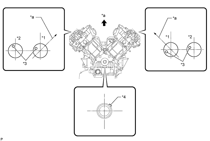
Text in Illustration *1 IN *2 EX *3 Knock Pin *4 Key *a Toward Ceiling - -
-
-
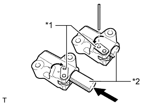
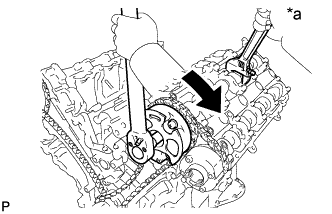
INSTALL NO. 2 CHAIN TENSIONER ASSEMBLY
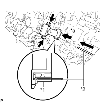
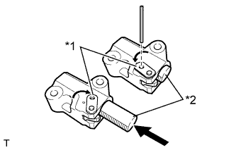
Text in Illustration *1 Plunger *2 Pin *a Push
-
Install the chain tensioner with the 2 bolts.
- Torque:
- 10 N*m { 102 kgf*cm, 7 ft.*lbf }
-
While raising up the No. 2 chain tensioner, insert a pin of 1.0 mm (0.0394 in.) into the hole to fix it in place.
-
-
INSTALL NO. 1 CHAIN SUB-ASSEMBLY RH
-
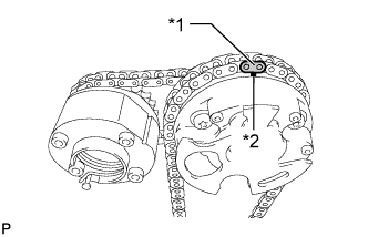
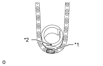
Text in Illustration *1 Mark Plate *2 Timing Mark Align the No. 1 chain orange mark plate with the camshaft timing gear timing mark, and attach the chain to the gear as shown in the illustration.
-
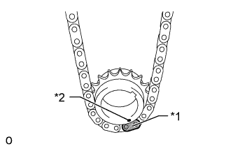
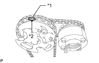
Text in Illustration *1 Mark Plate *2 Timing Mark Align the No. 1 chain orange mark plate with the crankshaft timing sprocket timing mark, and attach the chain to the gear as shown in the illustration.
-
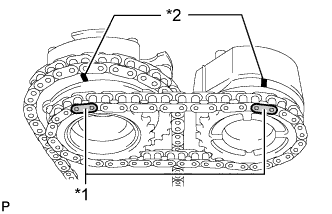
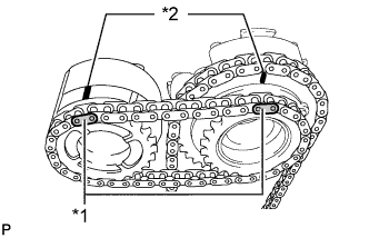
Text in Illustration *1 Mark Plate *2 Timing Mark Align the No. 2 chain yellow mark plates with the timing marks of the camshaft timing gear assembly and camshaft timing exhaust gear assembly, and attach the No. 2 chain to the gears as shown in the illustration.
Tech Tips
The crankshaft timing sprocket RH and camshaft timing exhaust gear will be installed with the No. 1 and No. 2 chains connected to the gears.
-
Install the crankshaft timing sprocket RH to the crankshaft.
-
Align and attach the knock pin of the No. 1 camshaft with the pin hole of the camshaft timing gear.
-
Using the hexagonal portion of the No. 2 camshaft, align and attach the knock pin of the No. 2 camshaft with the pin hole of the camshaft timing exhaust gear.
-
Remove the pin from the No. 2 chain tensioner.
-
Using a wrench to hold the hexagonal portion of the No. 1 camshaft, temporarily install the bolt.
-
Using a wrench to hold the hexagonal portion of the No. 2 camshaft, temporarily install the bolt.
-
-
INSTALL NO. 1 CHAIN VIBRATION DAMPER RH
-
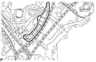
Install the vibration damper with the 2 bolts.
- Torque:
- 21 N*m { 214 kgf*cm, 15 ft.*lbf }
-
-
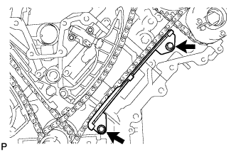
INSTALL NO. 1 CHAIN TENSIONER SLIPPER RH
Tech Tips
If you cannot install the chain tensioner slipper due to the tension of the chain, use the hexagonal portion of the camshaft to loosen the chain, and then install the chain tensioner slipper.
-
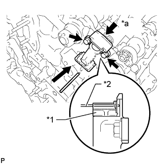
INSTALL NO. 1 CHAIN TENSIONER ASSEMBLY RH
Text in Illustration *1 Stopper Plate *2 Plunger
-
Move the stopper plate clockwise to release the lock, and push the plunger deep into the tensioner.
-
Move the stopper plate counterclockwise to set the lock, and insert a hexagon wrench into the hole of the stopper plate.
-
Install the chain tensioner with the 2 bolts.
- Torque:
- 10 N*m { 102 kgf*cm, 7 ft.*lbf }
-
Remove the hexagon wrench from the chain tensioner.
-
-
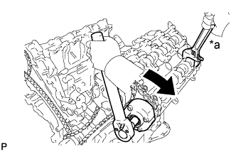
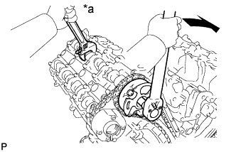
INSTALL NO. 3 CHAIN TENSIONER ASSEMBLY
Text in Illustration *1 Plunger *2 Pin *a Push
-
Install the chain tensioner with the 2 bolts.
- Torque:
- 10 N*m { 102 kgf*cm, 7 ft.*lbf }
-
While pushing down the No. 2 chain tensioner, insert a pin of 1.0 mm (0.0394 in.) into the hole to fix it in place.
-
-
INSTALL NO. 1 CHAIN SUB-ASSEMBLY LH
-
Text in Illustration *1 Mark Plate *2 Timing Mark Align the No. 1 chain orange mark plate with the camshaft timing gear timing mark, and attach the chain to the gear as shown in the illustration.
-
Text in Illustration *1 Mark Plate *2 Timing Mark Align the No. 1 chain orange mark plate with the crankshaft timing sprocket timing mark, and attach the chain to the gear as shown in the illustration.
-
Text in Illustration *1 Mark Plate *2 Timing Mark Align the No. 2 chain yellow mark plates with the timing marks of the camshaft timing gear assembly and camshaft timing exhaust gear assembly, and attach the No. 2 chain to the gears as shown in the illustration.
Tech Tips
The crankshaft timing sprocket LH and camshaft timing exhaust gear will be installed with the No. 1 and No. 2 chains connected to the gears.
-
Install the crankshaft timing sprocket LH to the crankshaft.
-
Align and attach the knock pin of the No. 3 camshaft with the pin hole of the camshaft timing gear.
-
Using the hexagonal portion of the No. 4 camshaft, align and attach the knock pin of the No. 4 camshaft with the pin hole of the camshaft timing exhaust gear.
Note
Because the timing mark positions of the gears may shift due to looseness of the No. 1 chain, use the hexagonal portion of the camshaft to hold the No. 3 camshaft in place until the No. 1 chain tensioner is installed.
-
Remove the pin from the No. 3 chain tensioner.
-
Using a wrench to hold the hexagonal portion of the No. 3 camshaft, temporarily install the bolt.
-
Using a wrench to hold the hexagonal portion of the No. 4 camshaft, temporarily install the bolt.
-
-
INSTALL NO. 1 CHAIN TENSIONER SLIPPER LH
Tech Tips
If you cannot install the chain tensioner slipper due to the tension of the chain, use the hexagonal portion of the camshaft to loosen the chain, and install the chain tensioner slipper.
-
INSTALL NO. 1 CHAIN TENSIONER ASSEMBLY LH
Text in Illustration *1 Stopper Plate *2 Plunger
-
Move the stopper plate clockwise to release the lock, and push the plunger deep into the tensioner.
-
Move the stopper plate counterclockwise to set the lock, and insert a hexagon wrench into the hole of the stopper plate.
-
Install a new gasket and the chain tensioner with the 2 bolts.
- Torque:
- 10 N*m { 102 kgf*cm, 7 ft.*lbf }
-
-
INSTALL NO. 1 CHAIN VIBRATION DAMPER LH
-
Install the vibration damper with the 2 bolts.
- Torque:
- 21 N*m { 214 kgf*cm, 15 ft.*lbf }
-
Remove the hexagon wrench from the No. 1 chain tensioner.
-
-
TIGHTEN CAMSHAFT TIMING GEAR ASSEMBLY
-
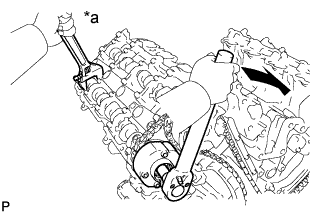
Text in Illustration *a Hold 
Turn for Bank 1:
-
Using a wrench, hold the hexagonal portion of the No. 3 camshaft.
-
Tighten the bolt of the camshaft timing gear.
- Torque:
- 100 N*m { 1020 kgf*cm, 74 ft.*lbf }
-
Text in Illustration *a Hold Turn Using a wrench to hold the hexagonal portion of the No. 4 camshaft, tighten the bolt of the camshaft timing exhaust gear.
- Torque:
- 100 N*m { 1020 kgf*cm, 74 ft.*lbf }
-
-
Text in Illustration *a Hold Turn for Bank 2:
-
Using a wrench, hold the hexagonal portion of the No. 1 camshaft.
-
Tighten the bolt of the camshaft timing gear.
- Torque:
- 100 N*m { 1020 kgf*cm, 74 ft.*lbf }
-
Text in Illustration *a Hold Turn Using a wrench to hold the hexagonal portion of the No. 2 camshaft, tighten the bolt of the camshaft timing exhaust gear.
- Torque:
- 100 N*m { 1020 kgf*cm, 74 ft.*lbf }
-
-
-
CHECK NO. 1 CYLINDER TO TDC/COMPRESSION
-
Temporarily install the crankshaft pulley bolt.
-
Rotate the crankshaft clockwise, and check that the timing marks on the crankshaft timing sprocket and camshaft timing gears are as shown in the illustration.
-
Remove the crankshaft pulley bolt.
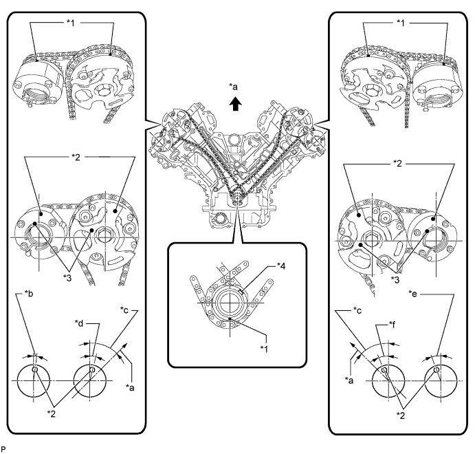
Text in Illustration *1 Timing Mark *2 Timing Mark Position *3 Knock Pin Position *4 Key *a Toward Ceiling *b Approximately 2° *c Approximately 45° *d Approximately 16° *e Approximately 18° *f Approximately 32°
-
-
INSTALL WATER INLET PIPE
-
Apply soapy water to 2 new O-rings and install them to the inlet pipe.
-
Install the inlet pipe to the No. 1 heat exchanger cover.
-
-
INSTALL TIMING CHAIN COVER SUB-ASSEMBLY
-
Apply a light coat of engine oil to a new oil pump gasket.
-
Install the oil pump gasket.
-
Apply a light coat of engine oil to a new O-ring.
-
Install the O-ring.
-
Apply seal packing in a continuous line to the timing chain cover as shown in the following illustration.
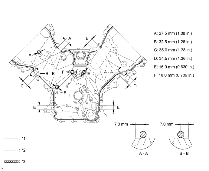
Text in Illustration *1 Continuous line area *2 Dashed line area *3 Diagonal line area - - Seal packing Toyota Genuine Seal Packing Black, Three Bond 1207B or equivalent
-
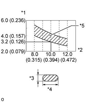
Text in Illustration *1 Seal Packing Thickness mm (in.) *2 Seal Packing Width mm (in.) *3 Seal Packing Thickness *4 Seal Packing Width *5 OK Area Apply Seal Packing as Follows Area Seal Packing Diameter Application Position from Inside Edge of Cover Continuous Line Area 3.0 to 4.0 mm (0.118 to 0.157 in.) 2.5 mm (0.0984 in.) Dashed Line Area 6.4 mm (0.252 in.) or more, or within OK area shown in illustration 7.0 mm (0.276 in.) Diagonal Line Area 3.0 to 4.0 mm (0.118 to 0.157 in.) 5.5 mm (0.217 in.)
Note
-
When the contact surfaces are wet, wipe them with an oil-free cloth before applying seal packing.
-
Install the chain cover within 3 minutes and tighten the bolts within 10 minutes after applying seal packing.
-
-
Align the oil pump drive rotor spline and crankshaft as shown in the illustration. Install the spline and chain cover to the crankshaft.
-
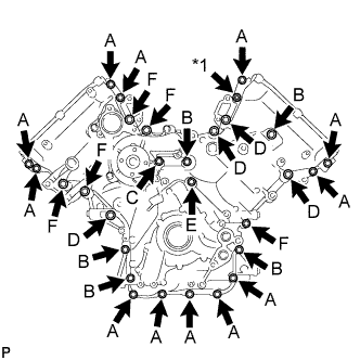
Text in Illustration *1 Nut Temporarily install the timing chain cover with the 28 bolts and nut.
Standard Bolt Item Length Thread Diameter Bolt A 25 mm (0.984 in.) 8 mm (0.315 in.) Bolt B 55 mm (2.17 in.) 8 mm (0.315 in.) Bolt C 70 mm (2.76 in.) 8 mm (0.315 in.) Bolt D 35 mm (1.38 in.) 10 mm (0.394 in.) Bolt E 55 mm (2.17 in.) 10 mm (0.394 in.) Bolt F 80 mm (3.15 in.) 10 mm (0.394 in.) Note
Make sure that there is no oil on the bolt threads.
-
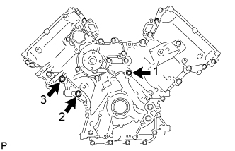
Tighten the 3 bolts in several steps in the sequence shown in the illustration.
- Torque:
- 47 N*m { 479 kgf*cm, 35 ft.*lbf }
-
Temporarily install the fluid coupling bracket with the 4 bolts.
Standard Bolt Item Length Thread Diameter Bolt A 70 mm (2.76 in.) 8 mm (0.315 in.) Bolt B 80 mm (3.15 in.) 10 mm (0.394 in.) -
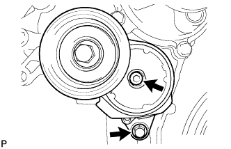
Temporarily install the belt tensioner with the standard bolt and 6 mm hexagon wrench bolt.
-
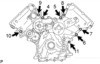
Tighten the 8 bolts labeled 4 to 11 in several steps in the sequence shown in the illustration.
- Torque:
- 47 N*m { 479 kgf*cm, 35 ft.*lbf }
-
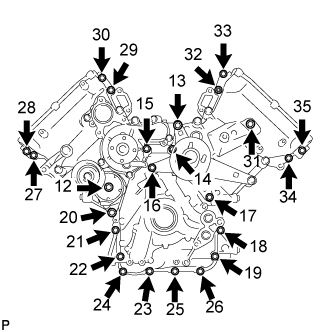
Tighten the 23 bolts and nut labeled 12 to 35 in several steps in the sequence shown in the illustration.
- Torque:
- 23 N*m { 235 kgf*cm, 17 ft.*lbf }
Note
-
Do not start the engine for at least 2 hours after installing.
-
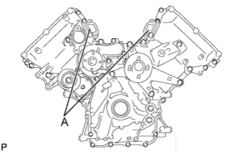
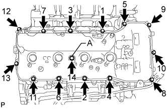
After the installation, if the seal packing has seeped out at the areas labeled A shown in the illustration, wipe it off.
-
-
INSTALL SPARK PLUG TUBE GASKET
-
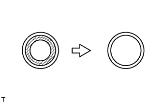
Using a cutter knife, cut off the seal part of the removed gasket.
Text in Illustration 
Area to cut off -
Text in Illustration *1 Removed Gasket *2 New Gasket Using the removed gasket and a hammer, tap in a new gasket until it stops.
Tech Tips
If the removed gasket does not fit on the new one, correct the removed one with pliers.
-
Apply a light coat of MP grease to the lip of the gasket.
-
Return the 4 ventilation baffle plate claws to the original positions.
-
-
INSTALL CYLINDER HEAD COVER SUB-ASSEMBLY LH
-
Install 5 new gaskets to the camshaft bearing caps (No. 2, No. 3).
-
Install a new gasket to the cylinder head cover.
Note
Remove any oil from the contact surface.
-
Apply seal packing as shown in the illustration.
Seal packing Toyota Genuine Seal Packing Black, Three Bond 1207B or equivalent Text in Illustration Seal Packing Note
-
Remove any oil from the contact surface.
-
Install the cylinder head cover within 3 minutes and tighten the bolts within 15 minutes after applying seal packing.
-
-
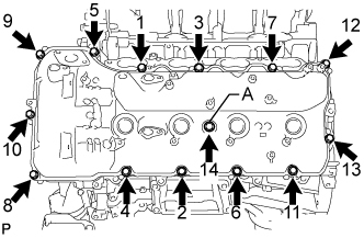
Install the cylinder head cover and a new seal washer with the 14 bolts in the order shown in the illustration.
- Torque:
- for bolt A
- 21 N*m { 214 kgf*cm, 15 ft.*lbf }
- except bolt A
- 12 N*m { 122 kgf*cm, 9 ft.*lbf }
Note
Do not start the engine for at least 2 hours after the installation.
-
-
INSTALL CYLINDER HEAD COVER SUB-ASSEMBLY RH
-
Install 5 new gaskets to the camshaft bearing caps. (No. 1, No. 3).
-
Install a new gasket to the cylinder head cover.
Note
Remove any oil from the contact surface.
-
Apply seal packing as shown in the illustration.
Seal packing Toyota Genuine Seal Packing Black, Three Bond 1207B or equivalent Text in Illustration Seal Packing Note
-
Remove any oil from the contact surface.
-
Install the cylinder head cover within 3 minutes and tighten the bolts within 15 minutes after applying seal packing.
-
-
Install the cylinder head cover and a new seal washer with the 14 bolts in the order shown in the illustration.
- Torque:
- for bolt A
- 21 N*m { 214 kgf*cm, 15 ft.*lbf }
- except bolt A
- 12 N*m { 122 kgf*cm, 9 ft.*lbf }
Note
Do not start the engine for at least 2 hours after the installation.
-
Install the noise filter to the cylinder head cover with the bolt.
- Torque:
- 7.0 N*m { 71 kgf*cm, 62 in.*lbf }
-
-
INSTALL IGNITION COIL ASSEMBLY
-
Install the 8 ignition coils with the 8 bolts.
- Torque:
- 10 N*m { 102 kgf*cm, 7 ft.*lbf }
-
-
INSTALL CRANKSHAFT TIMING GEAR KEY
-
Install the timing gear key.
Tech Tips
The other timing gear key will be installed at a later step.
-
-
INSTALL CRANKSHAFT PULLEY
-
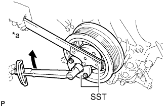
Text in Illustration *a Hold Turn Align the pulley set key with the key groove of the pulley, and slide on the pulley.
-
Using SST, install the pulley set bolt.
- SST
- 09213-70011
- 09330-00021
- Torque:
- 300 N*m { 3059 kgf*cm, 221 ft.*lbf }
-
-
CONNECT WIRE HARNESS CLAMP BRACKET
-
Connect the bracket to the timing chain cover with the bolt.
- Torque:
- 8.0 N*m { 82 kgf*cm, 71 in.*lbf }
-
-
INSTALL NO. 1 IDLER PULLEY SUB-ASSEMBLY
-
Install the idler pulley with the bolt.
- Torque:
- 43 N*m { 438 kgf*cm, 32 ft.*lbf }
-
-
INSTALL WATER PUMP PULLEY
-
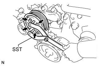
Temporarily install the pulley with the 4 bolts.
-
Using SST, hold the pulley and tighten the 4 bolts.
- SST
- 09960-10010 ( 09962-01000, 09963-01000 )
- Torque:
- 21 N*m { 214 kgf*cm, 15 ft.*lbf }
-
-
INSTALL WATER INLET HOUSING
-
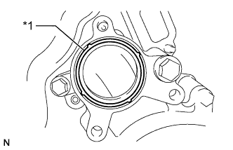
Text in Illustration *1 Gasket Install a new gasket to the timing chain cover.
-
Install the water inlet with the 3 bolts.
- Torque:
- 21 N*m { 214 kgf*cm, 15 ft.*lbf }
-
-
INSTALL NO. 1 ENGINE COVER
-
INSTALL NO. 2 ENGINE COVER
-
INSTALL FRONT WATER BY-PASS JOINT
-
Install 2 new gaskets and the water by-pass joint with the 4 nuts.
- Torque:
- 21 N*m { 214 kgf*cm, 15 ft.*lbf }
-
Connect the No. 2 water by-pass hose to the water by-pass joint.
-
-
INSTALL WATER BY-PASS PIPE SUB-ASSEMBLY
-
Connect the 2 hoses.
-
Install the water by-pass pipe with the 2 bolts.
- Torque:
- 10 N*m { 102 kgf*cm, 7 ft.*lbf }
-
-
INSTALL NO. 1 WATER BY-PASS HOSE
-
Install the No. 1 water by-pass hose by connecting the hose to the water inlet housing and front water by-pass joint.
-
-
INSTALL GENERATOR ASSEMBLY
-
Install the stud bolt.
- Torque:
- 10 N*m { 102 kgf*cm, 7 ft.*lbf }
-
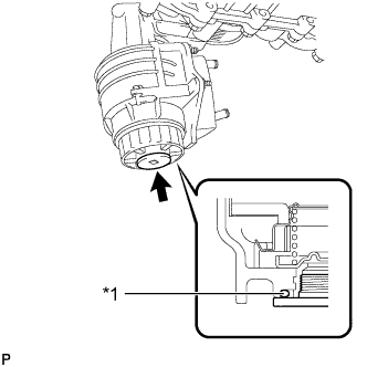
Install the generator with the 3 bolts and nut.
- Torque:
- 43 N*m { 438 kgf*cm, 32 ft.*lbf }
-
Connect the harness bracket to the generator with the bolt.
- Torque:
- 31 N*m { 316 kgf*cm, 23 ft.*lbf }
-
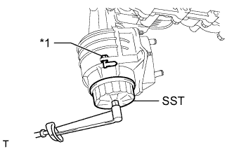
Connect the generator wire with the nut.
- Torque:
- 9.8 N*m { 100 kgf*cm, 87 in.*lbf }
-
Close the terminal cap.
-
Connect the generator connector.
-
-
CONNECT OIL COOLER PIPE ASSEMBLY
-
Подсоедините трубку масляного радиатора и закрепите 2 болтами.
- Torque:
- 14 Н*м { 143 кгс*см, 10 фунт-сила-футов }
-
-
CONNECT VANE PUMP ASSEMBLY
Tech Tips
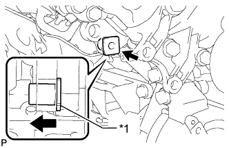
Before performing the following procedures, move the spacer until the vane pump can be installed.
Text in Illustration *1 Spacer
-
Connect the vane pump to the timing chain cover with the 2 bolts.
- Torque:
- 21 N*m { 214 kgf*cm, 15 ft.*lbf }
-
-
INSTALL INTAKE MANIFOLD
-
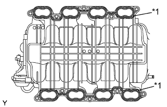
Text in Illustration *1 Gasket Place 2 new gaskets on the intake manifold.
-
Place the intake manifold on the cylinder head.
-
Install and uniformly tighten the 8 bolts and 2 nuts in several steps.
- Torque:
- 21 N*m { 214 kgf*cm, 15 ft.*lbf }
-
Install the wire bracket to the intake manifold with the bolt.
- Torque:
- 8.0 N*m { 82 kgf*cm, 71 in.*lbf }
-
Connect the 3 wire clamps to the 3 wire brackets.
-
Install the No. 3 engine cover.
-
Install the No. 1 engine cover sub-assembly.
-
Connect the purge VSV connector.
-
Connect the purge line hose to the purge VSV.
-
Connect the vacuum switching valve connector (for ACIS).
-
Connect the No. 1 ventilation hose.
-
Connect the 2 water by-pass hoses.
-
Connect the throttle body connector.
-
Connect the ventilation hose to the ventilation pipe of the cylinder head cover LH and RH.
-
-
INSTALL OIL FILTER BRACKET
-
Apply a light coat of engine oil to 2 new O-rings.
-
Install the 2 O-rings to the timing chain cover.
-
Install the oil filter bracket with the 2 nuts and 2 bolts.
- Torque:
- 35 N*m { 357 kgf*cm, 26 ft.*lbf }
-
-
INSTALL NO. 1 OIL COOLER BRACKET
-
Connect the ground wire to the cylinder block.
-
Install the oil cooler bracket with the 2 nuts.
- Torque:
- 21 N*m { 214 kgf*cm, 15 ft.*lbf }
-
-
INSTALL NO. 2 WATER BY-PASS PIPE SUB-ASSEMBLY
-
Connect the 4 hoses.
-
Install the water by-pass pipe with the 3 bolts.
- Torque:
- 10 N*m { 102 kgf*cm, 7 ft.*lbf }
-
-
INSTALL OIL PRESSURE SENDER GAUGE ASSEMBLY
-
Apply adhesive to 2 or 3 threads of the oil pressure sender gauge.
Adhesive Toyota Genuine Adhesive 1344, Three Bond 1344 or equivalent Note
Do not allow adhesive to contact the oil hole.
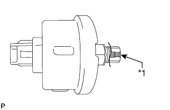
Text in Illustration *1 Oil Hole -
Install the oil pressure sender gauge.
- Torque:
- 15 N*m { 153 kgf*cm, 11 ft.*lbf }
Note
Do not start the engine within 1 hour after installation.
-
Connect the sender gauge connector.
-
-
INSTALL ENGINE OIL LEVEL DIPSTICK GUIDE
-
Нанесите на новое кольцевое уплотнение тонкий слой моторного масла.
-
Установите кольцевое уплотнение на направляющую.
-
Закрепите трубку щупа проверки уровня масла болтом.
- Torque:
- 10 Н*м { 102 кгс*см, 7 фунт-сила-футов }
-
Установите щуп проверки уровня масла.
-
Присоедините зажим жгута проводов.
-
-
INSTALL OIL FILTER ELEMENT
-
Clean the inside of the oil filter cap, its threads and its O-ring groove.
-
Apply a small amount of engine oil to a new O-ring and install it to the oil filter cap.
-
Set a new oil filter element to the oil filter cap.
-
Remove any dirt or foreign matter from the installation surface of the engine.
-
Apply a small amount of engine oil to the O-ring again and temporarily install the oil filter cap.
Note
Do not remove the oil filter bracket clip.
-
Text in Illustration *1 Oil Filter Bracket Clip Using SST, tighten the oil filter cap.
- SST
- 09228-06501
- Torque:
- 25 N*m { 255 kgf*cm, 18 ft.*lbf }
Note
-
When tightening the oil filter cap, do not remove the oil filter bracket clip.
-
Make sure that the oil filter is installed securely as shown in the illustration.
-
Be careful that the O-ring does not get caught between any surrounding parts.
-
Text in Illustration *1 O-Ring Apply a small amount of engine oil to a new drain plug O-ring, and install it to the oil filter cap.
Note
Before installing the O-ring, remove any dirt or foreign matter from the installation surface of the oil filter cap.
-
Install the oil filter drain plug.
- Torque:
- 13 N*m { 127 kgf*cm, 9 ft.*lbf }
Note
Be careful that the O-ring does not get caught between any surrounding parts.
-
Install the No. 2 engine under cover seal with the 2 bolts.
- Torque:
- 10 N*m { 102 kgf*cm, 7 ft.*lbf }
-
-
CONNECT NO. 2 FUEL TUBE SUB-ASSEMBLY
-
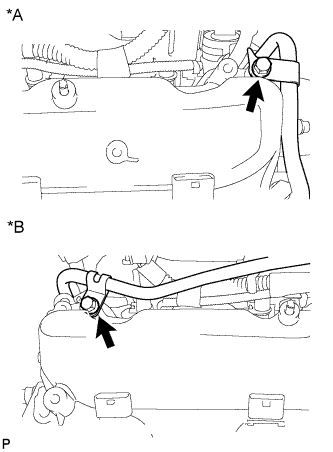
Text in Illustration *A LH Side *B RH Side Connect the fuel tube with the 2 bolts.
- Torque:
- 10 N*m { 102 kgf*cm, 7 ft.*lbf }
-
-
CONNECT COOLER COMPRESSOR ASSEMBLY
-
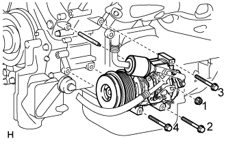
Install the cooler compressor with the stud bolt.
- Torque:
- 10 N*m { 102 kgf*cm, 7 ft.*lbf }
-
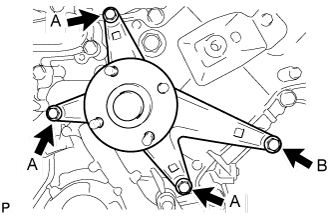
Install the 3 bolts and nut.
- Torque:
- 25 N*m { 250 kgf*cm, 18 ft.*lbf }
Note
Tighten the bolts and nut in the order shown in the illustration to install the cooler compressor.
-
-
CONNECT WATER PIPE AND HOSE SUB-ASSEMBLY
-
Connect the water pipe and hose to the cylinder head cover with the 2 bolts.
- Torque:
- 18 N*m { 184 kgf*cm, 13 ft.*lbf }
-
Connect the 3 hoses.
-
-
CONNECT ENGINE WIRE
-
Connect the 2 clamps and power steering oil pressure switch connector.
-
Engine Room RH Side:
-
Connect the 5 clamps.
-
Connect the throttle position sensor and throttle control motor connector.
-
Install the ground wire with the 2 bolts.
- Torque:
- 8.0 N*m { 82 kgf*cm, 71 in.*lbf }
-
Connect the noise filter connector.
-
Connect the 2 VVT sensor connectors.
-
Connect the injector connector.
-
Connect the 4 ignition coil connectors.
-
Connect the 2 camshaft timing oil control valve connectors.
-
-
Engine Room LH Side:
-
Connect the cooler compressor connector.
-
Connect the 3 clamps.
-
Connect the camshaft position sensor connector.
-
Connect the 2 camshaft timing oil control valve connectors.
-
Connect the engine coolant temperature sensor connector.
-
Connect the 4 clamps.
-
Install the ground wire with the 2 bolts.
- Torque:
- 8.0 N*m { 82 kgf*cm, 71 in.*lbf }
-
Connect the noise filter connector.
-
Connect the 2 VVT sensor connectors.
-
Connect the 4 ignition coil connectors.
-
Connect the injector connector.
-
Connect the 2 connectors and 2 clips to the engine room junction block.
-
Install the engine room relay block cover.
-
-
-
INSTALL RADIATOR ASSEMBLY
-
Set the radiator bracket hooks to the radiator support holes.
-
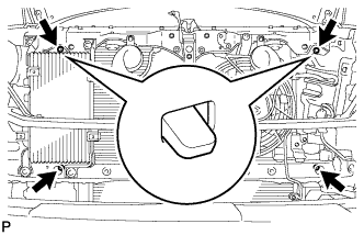
Install the radiator with the 4 bolts.
- Torque:
- 18 N*m { 184 kgf*cm, 13 ft.*lbf }
-
Connect the 2 oil cooler hoses.
-
-
INSTALL FAN SHROUD
-
Install the fan pulley.
-
Place the shroud together with the coupling fan between the radiator and engine.
Note
Be careful not to damage the radiator core.
-
Temporarily install the fluid coupling fan to the fluid coupling bracket with the 4 nuts. Tighten the nuts as much as possible by hand.
-
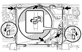
Attach the claws of the shroud to the radiator as shown in the illustration.
-
Install the shroud with the 2 bolts.
- Torque:
- 8.0 N*m { 82 kgf*cm, 71 in.*lbf }
-
Connect the oil cooler tube to the fan shroud with the 2 bolts.
- Torque:
- 5.0 N*m { 51 kgf*cm, 44 in.*lbf }
-
Pass the hose through the flexible hose clamp and close the clamp as shown in the illustration.
-
Connect the reservoir hose to the upper radiator tank.
-
Install the fan and generator V-belt Click here.
-
Tighten the 4 nuts of the fluid coupling fan.
- Torque:
- 21 N*m { 214 kgf*cm, 15 ft.*lbf }
-
-
INSTALL NO. 2 RADIATOR HOSE
-
INSTALL NO. 1 RADIATOR HOSE
-
INSTALL AIR CLEANER ASSEMBLY
-
Установите воздушный фильтр и закрепите его 3 болтами.
- Torque:
- 5,0 Н*м { 51 кгс*см, 44 фунт-сила-дюйма }
-
-
INSTALL AIR CLEANER HOSE ASSEMBLY
-
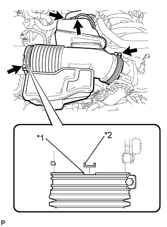
Text in Illustration *1 Groove *2 Protrusion Install the air cleaner hose so that the protrusion of the air cleaner cap aligns with the groove of the hose as shown in the illustration.
-
Tighten the 2 clamps.
- Torque:
- 2.5 N*m { 25 kgf*cm, 22 in.*lbf }
-
Connect the vacuum hose.
-
Connect the No. 2 ventilation hose.
-
-
INSTALL V-BANK COVER SUB-ASSEMBLY
-
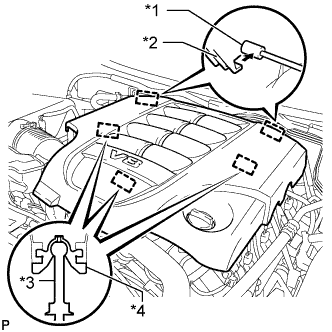
Обозначения на рисунке *1 Кронштейн *2 Крепежный крюк *3 Штифт *4 Уплотнительная шайба Совместите 2 крюка крышки V-образного двигателя с кронштейном. Затем совместите 3 уплотнительных шайбы декоративной крышки V-образного двигателя с 3 штифтами и нажмите на декоративную крышку V-образного двигателя, чтобы закрепить штифты.
-
-
ADD ENGINE OIL
-
Add fresh oil and install the oil filler cap.
Standard Oil Grade Oil Grade Oil Viscosity (SAE) API grade SL "energy-conserving", API grade SM "energy-conserving", API grade SN "energy-conserving" or ILSAC multigrade engine oil 5W-30
10W-30
API grade SL, SM or SN multigrade engine oil 15W-40
20W-50
Standard Oil Capacity Item Specified Condition Drain and refill without oil filter change 7.1 liters (7.5 US qts, 6.2 Imp. qts) Drain and refill with oil filter change 7.5 liters (7.9 US qts, 6.6 Imp. qts) Dry fill 9.3 liters (9.8 US qts, 8.2 Imp. qts)
-
-
ADD ENGINE COOLANT
-
Долейте охлаждающую жидкость.
Номинальный объем Параметр / Устройство Заданные условия Для моделей с задним отопителем 16,2 л (17,1 кварты США, 14,3 английской кварты) Для моделей без заднего отопителя 13,4 литра (14,2 кварты США, 11,8 английской кварты) Note
Не доливайте простую воду вместо охлаждающей жидкости двигателя.
Tech Tips
Автомобили Toyota первоначально заправляются охлаждающей жидкостью TOYOTA SLLC на заводе. Во избежание повреждения системы охлаждения двигателя или других технических проблем разрешается использовать только охлаждающую жидкость "TOYOTA Super Long Life Coolant" или аналогичную высококачественную охлаждающую жидкость на основе этиленгликоля (а не на силикатной, аминовой, нитритной или борнокислой основе), изготовленную по гибридной технологии органических кислот с длительным сроком годности (охлаждающая жидкость, изготовленная по гибридной технологии органических кислот, состоит из низкофосфатных соединений и органических кислот).
-
Медленно налейте охлаждающую жидкость в расширительный бачок радиатора до отметки "F".
-
Установите пробку расширительного бачка.
-
Несколько раз сожмите рукой патрубки радиатора № 1 и № 2, а затем проверьте уровень охлаждающей жидкости. Если уровень охлаждающей жидкости недостаточен, добавьте жидкость.
-
Установите на место пробку радиатора.
-
Запустите двигатель и прогрейте его до открывания термостата.
Tech Tips
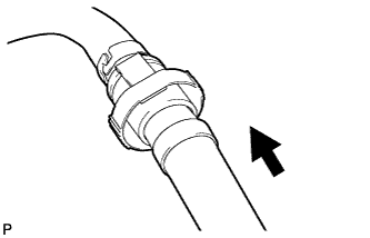
Время открывания термостата можно проверить, сжав входной патрубок радиатора рукой и убедившись, что охлаждающая жидкость поступает в шланг.
-
Поддерживайте частоту вращения коленчатого вала двигателя 2000–2500 об/мин.
Note
-
Убедитесь, что в расширительном бачке радиатора осталась охлаждающая жидкость.
-
Обратите внимание на стрелку датчика температуры охлаждающей жидкости. Убедитесь, что значение температуры не превышает норму.
-
В случае недостатка охлаждающей жидкости двигатель может закипеть или перегреться.
-
Если в расширительном бачке радиатора нет охлаждающей жидкости, сразу после запуска двигателя выполните следующие действия: 1) остановите двигатель, 2) подождите, пока охлаждающая жидкость остынет, и 3) долейте охлаждающую жидкость до линии "F".
-
Запустите двигатель, обеспечив частоту вращения коленчатого вала 2000 об/мин, и дайте ему поработать, пока уровень охлаждающей жидкости не стабилизируется.
-
-
Несколько раз сожмите патрубки радиатора № 1 и № 2 рукой, чтобы удалить воздух.
CAUTION:
-
Работайте в защитных перчатках.
-
Будьте осторожны: патрубки радиатора горячие.
-
Не приближайте свои руки к вентилятору.
-
-
Остановите двигатель и подождите, пока охлаждающая жидкость остынет до температуры окружающего воздуха.
CAUTION:
Не снимайте пробку радиатора, пока двигатель и радиатор не остынут. Выброс горячей охлаждающей жидкости и пара под давлением может стать причиной серьезных ожогов.
-
Убедитесь, что уровень охлаждающей жидкости находится между отметками "F" и "L".
Если уровень охлаждающей жидкости ниже линии "L", повторите рассмотренные выше операции.
Если уровень охлаждающей жидкости выше уровня "F", слейте охлаждающую жидкость до уровня между отметками "F" и "L".
-
-
CONNECT CABLE TO NEGATIVE BATTERY TERMINAL
Note
When disconnecting the cable, some systems need to be initialized after the cable is reconnected Click here.
-
INSPECT FOR OIL LEAK
-
Start the engine. Make sure that there are no oil leaks from the area that was worked on.
-
-
INSPECT FOR COOLANT LEAK
CAUTION:
Не снимайте пробку радиатора, пока двигатель и радиатор не остынут. Выброс горячей охлаждающей жидкости и пара под давлением может стать причиной серьезных ожогов.
-
Заполните радиатор охлаждающей жидкостью и подсоедините приспособление для опрессовки системы охлаждения и проверки пробки радиатора.
-
Прогрейте двигатель.
-
С помощью приспособления для опрессовки системы охлаждения и проверки пробки радиатора увеличьте давление в радиаторе до 123 кПа (1,3 кгс/см2, 18 фунтов на кв. дюйм) и убедитесь, что давление не падает.
Если давление снижается, проверьте на наличие утечек шланги, радиатор и насос системы охлаждения. При отсутствии внешних утечек проверьте сердцевину нагревателя, блок цилиндров и головку.
-
-
INSPECT ENGINE OIL LEVEL
-
Прогрейте двигатель. Затем остановите двигатель и подождите 5 секунд.
-
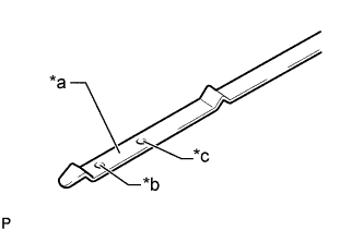
Обозначения на рисунке *a Измерительная поверхность *b Отметка низкого уровня *c Отметка полного уровня Убедитесь, что уровень моторного масла находится между отметками низкого и максимального уровней на щупе проверки уровня масла.
Если уровень масла находится на низком уровне, убедитесь в отсутствии утечек моторного масла и долейте масло до максимальной отметки.
Note
Не заливайте моторное масло выше максимальной отметки.
Tech Tips
Во время движения может быть израсходовано некоторое количество моторного масла. В указанных ниже ситуациях расход масла может возрасти, и может потребоваться добавление масла в промежутках между операциями технического обслуживания.
-
В случае нового двигателя, например непосредственно после покупки автомобиля или после замены двигателя.
-
При использовании низкокачественного масла или масла с несоответствующей вязкостью.
-
При движении с большой частотой вращения коленчатого вала двигателя или с большой нагрузкой (например, при буксировке), либо при движении с частым разгоном или замедлением.
-
При длительной работе двигателя на холостом ходу, либо при движении с частыми остановками в условиях дорожных пробок.
При определении расхода масла следует иметь в виду, что масло может разбавляться. Это затрудняет точное определение истинного уровня масла.
-
-
-
INSPECT IGNITION TIMING
-
Warm up and stop the engine.
-
Allow the engine to warm up to a normal operating temperature.
-
-
When using the intelligent tester:
-
Connect the intelligent tester to the DLC3.
-
Start the engine and idle it.
-
Turn the intelligent tester on.
-
Enter the following menus: Powertrain / Engine and ECT / Data List / Primary / IGN Advance.
Tech Tips
Refer to the intelligent tester operator's manual for further details.
Standard ignition timing 8 to 12° BTDC @ idling (transmission in neutral and A/C switch off) -
Disconnect the intelligent tester from the DLC3.
-
-
When not using the intelligent tester:
-
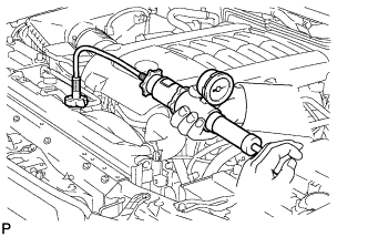
Connect the tester probe of a timing light to the wire of the ignition coil connector for the No. 1 cylinder.
Note
Use a timing light that detects primary signals.
-
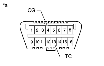
Text in Illustration *a Front view of DLC3 Using SST, connect terminals 13 (TC) and 4 (CG) of the DLC3.
- SST
- 09843-18040
Note
-
Confirm the terminal numbers before connecting them. Connecting the wrong terminals can damage the engine.
-
Switch off all accessories and the A/C before connecting the terminals.
-
Using the timing light, check the ignition timing.
Standard ignition timing 8 to 12° BTDC @ idling (transmission in neutral and A/C switch off) -
Remove SST from the DLC3.
-
Check the ignition timing.
Standard ignition timing 7 to 24° BTDC @ idling (transmission in neutral and A/C switch off) -
Disconnect the timing light from the engine.
-
-
-
INSPECT ENGINE IDLE SPEED
-
Warm up and stop the engine.
-
Allow the engine to warm up to a normal operating temperature.
-
-
When using the intelligent tester:
-
Connect the intelligent tester to the DLC3.
Note
Switch off all accessories and the A/C before connecting the intelligent tester.
-
Race the engine at 2500 rpm for approximately 90 seconds.
-
Turn the intelligent tester on.
-
Enter the following menus: Powertrain / Engine and ECT / Data List / Primary / Engine Speed.
Standard idle speed 650 to 750 rpm (transmission in neutral and A/C switch off) Tech Tips
Refer to the intelligent tester operator's manual for further details.
If the idle speed is not as specified, check the air intake system.
-
Disconnect the intelligent tester from the DLC3.
-
-
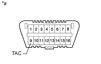
Text in Illustration *a Front view of DLC3 When not using the intelligent tester:
-
Using SST, connect the tachometer probe to terminal 9 (TAC) of the DLC3.
- SST
- 09843-18030
Note
-
Confirm the terminal number before connecting the probe. Connecting the probe to the wrong terminal can damage the engine.
-
Switch off all accessories and the A/C before connecting the probe.
-
Race the engine at 2500 rpm for approximately 90 seconds.
-
Check the idle speed.
Standard idle speed 650 to 750 rpm (transmission in neutral and A/C switch off) If the idle speed is not as specified, check the air intake system.
-
Disconnect the tachometer probe from the DLC3.
-
-
-
INSTALL FRONT FENDER APRON SEAL FRONT RH
-
Закрепите уплотнение фартука крыла 3 фиксаторами.
-
-
INSTALL FRONT FENDER APRON SEAL LH
-
Закрепите уплотнение фартука крыла 3 фиксаторами.
-
-
INSTALL NO. 2 ENGINE UNDER COVER
-
Установите защиту картера двигателя № 2 и закрепите ее 2 болтами.
- Torque:
- 29 Н*м { 296 кгс*см, 21 фунт-сила-фут }
-
-
INSTALL NO. 1 ENGINE UNDER COVER SUB-ASSEMBLY
-
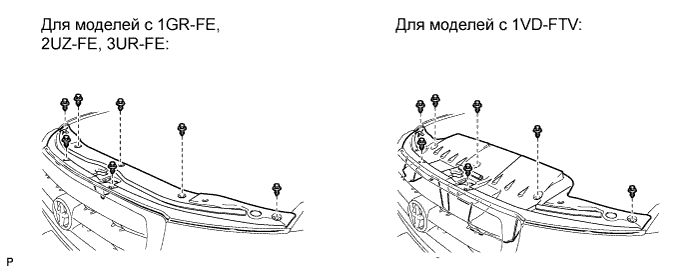
Установите защиту картера двигателя № 1 и закрепите ее 10 болтами.
- Torque:
- 29 Н*м { 296 кгс*см, 21 фунт-сила-фут }
-
-
INSTALL FRONT FENDER SPLASH SHIELD SUB-ASSEMBLY LH
-
Вставьте фиксатор, чтобы закрепить брызговик левого переднего крыла в сборе.
-
Вверните 3 болта и винт.
-
-
INSTALL FRONT FENDER SPLASH SHIELD SUB-ASSEMBLY RH
-
Вставьте фиксатор, чтобы закрепить брызговик правого переднего крыла в сборе.
-
Вверните 3 болта и 2 винта.
-
-
INSTALL COWL TOP VENTILATOR LOUVER SUB-ASSEMBLY
-
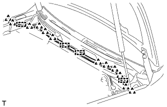
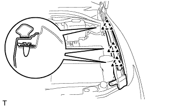
Надавите на вентиляционную решетку в направлении, указанном стрелкой на рисунке, чтобы ввести в зацепление 17 захватов и 2 фиксатора, и установите вентиляционную решетку.
-
-
INSTALL HOOD TO COWL TOP SEAL
-
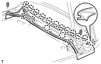
Введите в зацепление 12 фиксаторов и 4 зажима и установите уплотнение между капотом и решеткой радиатора.
-
Установите шланг стеклоомывателя.
-
-
INSTALL FRONT FENDER MAIN SEAL LH
-
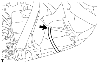
Введите в зацепление 3 фиксатора и установите основное уплотнение крыла.
-
-
INSTALL FRONT FENDER MAIN SEAL RH
Tech Tips
Порядок выполнения работ такой же, как для левой стороны.
-
INSTALL FRONT WIPER ARM LH
-
Остановите электродвигатель стеклоочистителя в положении автоматического ограничителя хода.
-
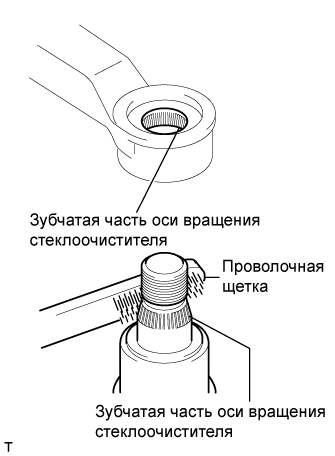
Почистите зубчатую часть оси вращения стеклоочистителя проволочной щеткой.
-
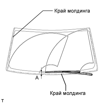
Установите рычаг и щетку стеклоочистителя и закрепите их гайкой. Убедитесь, что рычаг и щетка стеклоочистителя находятся в положении, показанном на рисунке.
Номинальная величина Положение Заданные условия А 16,8 - 36,8 мм (0,661 - 1,45 дюйма) - Torque:
- 25 Н*м { 255 кгс*см, 18 фунт-сила-футов }
Tech Tips
Удерживайте рукой шарнир рычага стеклоочистителя так, чтобы затянуть гайку.
-
-
INSTALL FRONT WIPER ARM RH
-
Остановите электродвигатель стеклоочистителя в положении автоматического ограничителя хода.
-
Почистите зубчатую часть оси вращения стеклоочистителя проволочной щеткой.
-
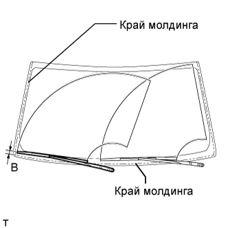
Установите рычаг и щетку стеклоочистителя и закрепите их гайкой. Убедитесь, что рычаг и щетка стеклоочистителя находятся в положении, показанном на рисунке.
Номинальная величина Положение Заданные условия B 20,0 - 40,0 мм (0,787 - 1,57 дюйма) - Torque:
- 25 Н*м { 255 кгс*см, 18 фунт-сила-футов }
Tech Tips
Удерживайте рукой шарнир рычага стеклоочистителя так, чтобы затянуть гайку.
-
Приведите в действие передние стеклоочистители, одновременно распыляя омывающую жидкость на ветровое стекло. Убедитесь, что передние стеклоочистители работают надлежащим образом и не задевают кузов автомобиля.
-
-
CONNECT RADIATOR SIDE DEFLECTOR LH
-
Connect the deflector with the 4 clips.
-
-
INSTALL TRANSMISSION OIL COOLER AIR DUCT
-
Install the oil cooler air duct with the 4 bolts.
- Torque:
- 4.9 N*m { 50 kgf*cm, 43 in.*lbf }
-
-
INSTALL FRONT BUMPER COVER
Tech Tips
Для облицовки переднего бампера с декоративной отделкой выполните описанные ниже действия.
-
Для моделей с системой очистителей фар:
Подсоедините шланг очистителя фар.
-
Для моделей с сенсорной системой помощи при парковке TOYOTA или противотуманными фарами:
Подсоедините разъем жгута электропроводки моторного отсека № 4.
-
Закрепите 10 захватов, чтобы установить накладку переднего бампера.
-
Установите 3 фиксатора и вверните 4 винта и 4 болта.
-
С помощью торцевого ключа с головкой "TORX" T30 вверните 6 винтов.
-
-
INSTALL RADIATOR GRILLE
-
Для моделей с широкоугольным монитором переднего вида и бокового обзора:
-
Подсоедините разъем.
-
-
Установите решетку радиатора в сборе и закрепите ее 2 фиксаторами и 8 захватами.
-
Вверните 3 винта.
-
-
INSTALL UPPER RADIATOR SUPPORT SEAL
-
Установите уплотнение кронштейна радиатора и закрепите его 7 фиксаторами.
-