РАСПРЕДВАЛ СНЯТИЕ
-
DISCHARGE FUEL SYSTEM PRESSURE
-
PRECAUTION
Note
After turning the engine switch off, waiting time may be required before disconnecting the cable from the battery terminal. Therefore, make sure to read the disconnecting the cable from the battery terminal notice before proceeding with work Click here.
-
DISCONNECT CABLE FROM NEGATIVE BATTERY TERMINAL
Note
When disconnecting the cable, some systems need to be initialized after the cable is reconnected Click here.
-
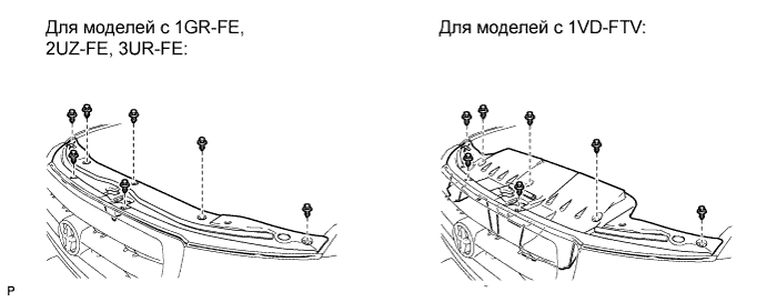
REMOVE UPPER RADIATOR SUPPORT SEAL
-
Освободите 7 фиксаторов и снимите уплотнение кронштейна радиатора.
-
-
REMOVE RADIATOR GRILLE
-
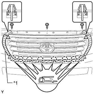
Обозначения на рисунке *1 Защитная клейкая лента Наклейте защитную клейкую ленту вокруг решетки радиатора.
-
Выверните 3 винта.
-
Отцепите 2 фиксатора и 8 захватов, а затем снимите решетку радиатора.
-
Для моделей с широкоугольным монитором переднего вида и бокового обзора:
-
Отсоедините разъем.
-
-
-
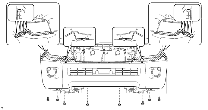
REMOVE FRONT BUMPER COVER
Tech Tips
Для облицовки переднего бампера с декоративной отделкой выполните описанные ниже действия.
-
Наклейте защитную ленту вокруг накладки переднего бампера.
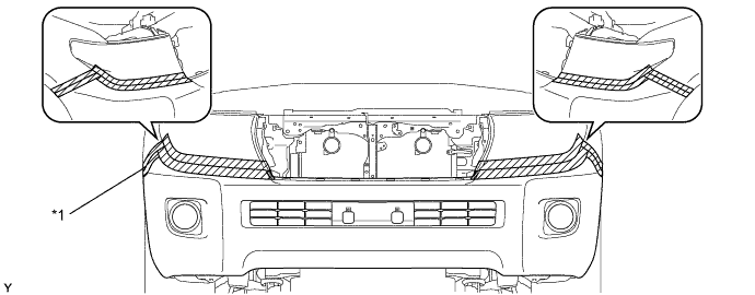
Обозначения на рисунке *1 Защитная клейкая лента - - -
С помощью торцевого ключа с головкой "TORX" T30 выверните 6 винтов.
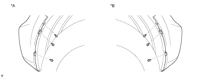
Обозначения на рисунке *A Левая сторона *B Правая сторона -
Снимите 3 фиксатора и выверните 4 винта и 4 болта.
-
Освободите 10 захватов и снимите накладку переднего бампера.
-
Для моделей с сенсорной системой помощи при парковке TOYOTA или противотуманными фарами:
Отсоедините разъем кабеля моторного отсека № 4 и снимите облицовку передний бампер.
-
Для моделей с системой очистителей фар:
Отсоедините шланг очистителя фар и снимите облицовку переднего бампера.
-
-
REMOVE TRANSMISSION OIL COOLER AIR DUCT
-
Remove the 4 bolts and oil cooler air duct.
-
-
DISCONNECT RADIATOR SIDE DEFLECTOR LH
-
Using a clip remover, remove the 4 clips and disconnect the side deflector.
-
-
REMOVE FRONT FENDER MAIN SEAL LH
-
С помощью съемника фиксаторов расцепите 3 фиксатора и снимите основное уплотнение крыла.
-
-
REMOVE FRONT FENDER MAIN SEAL RH
Tech Tips
Порядок выполнения работ такой же, как для левой стороны.
-
REMOVE FRONT WIPER ARM LH
-
Отверните гайку и снимите рычаг и щетку стеклоочистителя.
-
-
REMOVE FRONT WIPER ARM RH
-
Отверните гайку и снимите рычаг и щетку стеклоочистителя.
-
-
REMOVE HOOD TO COWL TOP SEAL
-
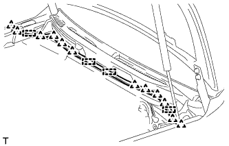
С помощью съемника фиксаторов расцепите 12 фиксаторов и 4 зажима и снимите верхнее уплотнение между капотом и кожухом.
-
-
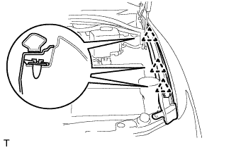
REMOVE COWL TOP VENTILATOR LOUVER SUB-ASSEMBLY
-
Снимите шланг омывателя.
-
Снимите 2 фиксатора.
-
Освободите 17 захватов и снимите вентиляционную решетку в верхней части кожуха в сборе.
-
-
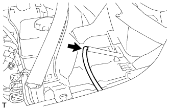
REMOVE FRONT FENDER SPLASH SHIELD SUB-ASSEMBLY LH
-
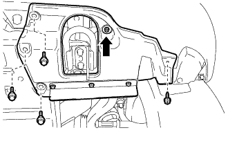
Выверните 3 болта и винт.
-
Поверните фиксатор, указанный стрелкой на рисунке, чтобы снять брызговик левого переднего крыла в сборе.
-
-
REMOVE FRONT FENDER SPLASH SHIELD SUB-ASSEMBLY RH
-
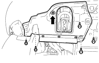
Выверните 3 болта и 2 винта.
-
Поверните фиксатор, указанный стрелкой на рисунке, чтобы снять брызговик правого переднего крыла в сборе.
-
-
REMOVE NO. 1 ENGINE UNDER COVER SUB-ASSEMBLY
-
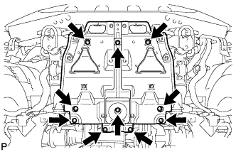
Выверните 10 болтов и снимите защиту картера двигателя № 1.
-
-
REMOVE NO. 2 ENGINE UNDER COVER
-
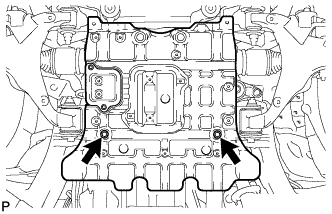
Выверните 2 болта и снимите защиту картера двигателя № 2.
-
-
REMOVE FRONT FENDER APRON SEAL LH
-

С помощью съемника фиксаторов снимите 3 фиксатора и уплотнение фартука крыла.
-
-
REMOVE FRONT FENDER APRON SEAL FRONT RH
-
С помощью съемника фиксаторов снимите 3 фиксатора и уплотнение фартука крыла.
-
-
DRAIN ENGINE OIL
-
Remove the oil filler cap.
-
Remove the 2 bolts and No. 2 engine under cover seal.
-
Remove the oil pan drain plug and gasket, and drain the engine oil into a container.
-
Install a new gasket and the oil pan drain plug.
- Torque:
- 40 N*m { 408 kgf*cm, 30 ft.*lbf }
-
-
DRAIN ENGINE COOLANT
CAUTION:
Не снимайте пробку радиатора, пока двигатель и радиатор не остынут. Выброс горячей охлаждающей жидкости и пара под давлением может стать причиной серьезных ожогов.
-
Ослабьте пробку сливного крана радиатора.
Tech Tips
Слейте охлаждающую жидкость в контейнер и утилизируйте ее в соответствии с местными требованиями.
-
Снимите пробку радиатора. Затем слейте охлаждающую жидкость из радиатора.
-
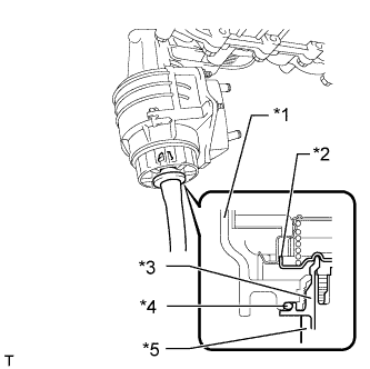
Ослабьте 2 пробки сливного крана блока цилиндров. Затем слейте охлаждающую жидкость из двигателя.
-
Затяните 2 пробки сливных кранов блока цилиндров.
- Torque:
- 13 Н*м { 133 кгс*см, 10 фунт-сила-футов }
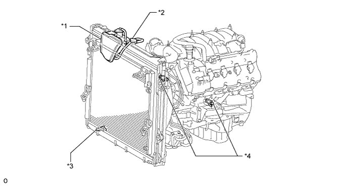
Обозначения на рисунке *1 Бачок радиатора *2 Пробка радиатора *3 Пробка сливного крана радиатора *4 Пробка сливного крана блока цилиндров -
Затяните пробку сливного крана радиатора вручную.
-
-
REMOVE V-BANK COVER SUB-ASSEMBLY
-
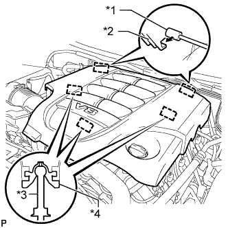
Обозначения на рисунке *1 Кронштейн *2 Крепежный крюк *3 Штифт *4 Уплотнительная шайба Поднимите переднюю часть декоративной крышки V-образного двигателя, чтобы открепить 3 штифта. Затем снимите 2 крюка декоративной крышки V-образного двигателя с кронштейна, чтобы снять декоративную крышку V-образного двигателя.
-
-
REMOVE AIR CLEANER HOSE ASSEMBLY
-
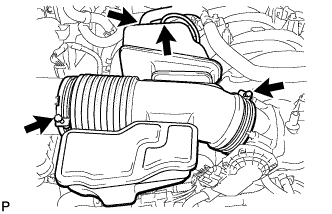
Отсоедините вакуумный шланг и шланг вентиляции картера № 2.
-
Ослабьте 2 хомута шланга.
-
Снимите шланг воздушного фильтра.
-
-
REMOVE AIR CLEANER ASSEMBLY
-
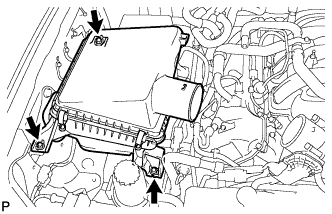
Выверните 3 болта и снимите воздушный фильтр.
-
-
REMOVE NO. 1 RADIATOR HOSE
-
REMOVE NO. 2 RADIATOR HOSE
-
REMOVE FAN SHROUD
-
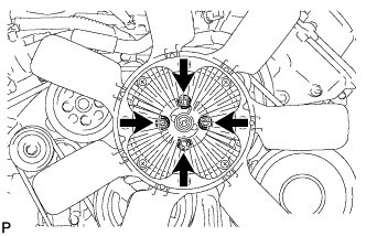
Loosen the 4 nuts holding the fluid coupling fan.
-
Remove the fan and generator V-belt Click here.
-
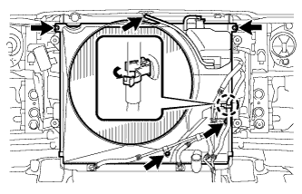
Disconnect the reservoir hose from the upper radiator tank.
-
Detach the claw to open the flexible hose clamp.
-
Remove the 2 bolts and disconnect the oil cooler tube from the fan shroud.
-
Remove the 2 bolts holding the fan shroud.
-
Remove the 4 nuts of the fluid coupling fan, and then remove the shroud together with the coupling fan.
Note
Be careful not to damage the radiator core.
-
Remove the fan pulley.
-
-
REMOVE RADIATOR ASSEMBLY
-
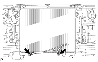
Disconnect the 2 oil cooler hoses.
-
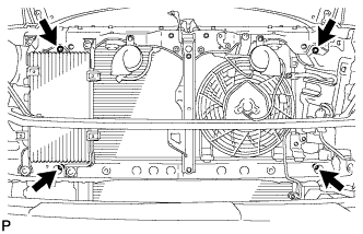
Remove the 4 bolts and radiator.
-
-
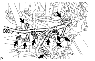
DISCONNECT ENGINE WIRE
-
Engine Room LH Side:
-
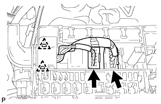
Remove the engine room relay block cover.
-
Disconnect the 2 connectors and 2 clips from the engine room junction block.
-
Disconnect the injector connector.
-
Disconnect the 4 ignition coil connectors.
-
Disconnect the 2 VVT sensor connectors.
-
Disconnect the 4 clamps.
-
Remove the 2 bolts and ground wire.
-
Disconnect the noise filter connector.
-
Disconnect the engine coolant temperature sensor connector.
-
Disconnect the 2 camshaft timing oil control valve connectors.
-
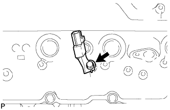
Disconnect the camshaft position sensor connector.
-
Disconnect the 3 clamps.
-
Disconnect the cooler compressor connector.
-
-
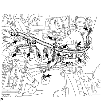
Engine Room RH Side:
-
Disconnect the 2 camshaft timing oil control valve connectors.
-
Disconnect the 4 ignition coil connectors.
-
Disconnect the injector connector.
-
Disconnect the 2 VVT sensor connectors.
-
Disconnect the noise filter connector.
-
Remove the 2 bolts and ground wire.
-
Disconnect the throttle position sensor and throttle control motor connector.
-
Disconnect the 5 clamps.
-
-
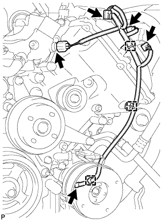
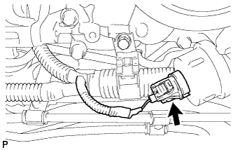
Disconnect the 2 clamps and power steering oil pressure switch connector.
-
-
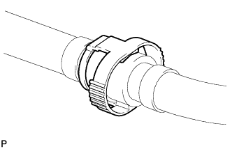
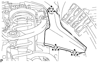
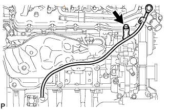
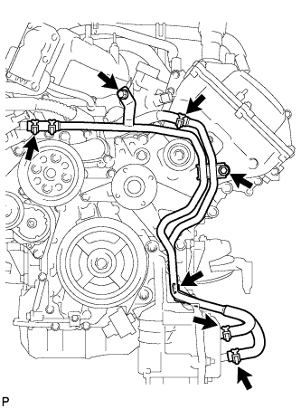
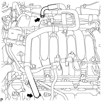
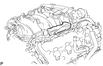
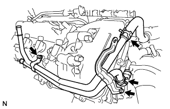
DISCONNECT WATER PIPE AND HOSE SUB-ASSEMBLY
-
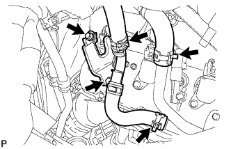
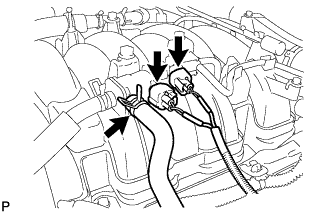
Disconnect the 3 hoses.
-
Remove the 2 bolts and disconnect the water pipe and hose from the cylinder head cover.
-
-
DISCONNECT COOLER COMPRESSOR ASSEMBLY
-
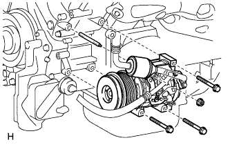
Remove the 3 bolts, nut and stud bolt, and disconnect the cooler compressor.
Tech Tips
It is not necessary to completely remove the compressor. With the hoses connected to the compressor, hang the compressor on the vehicle body with a rope.
-
-
DISCONNECT NO. 2 FUEL TUBE SUB-ASSEMBLY
-
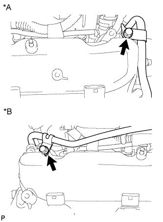
Text in Illustration *A LH Side *B RH Side Remove the 2 bolts and disconnect the fuel tube.
-
-
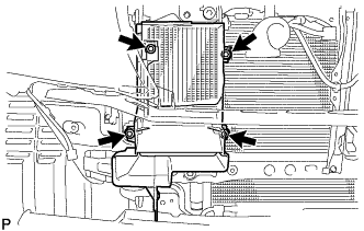
REMOVE OIL FILTER ELEMENT
-
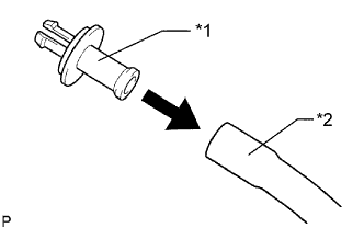
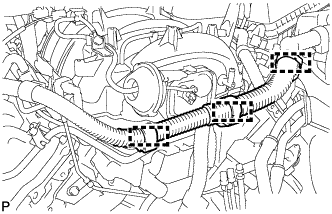
Text in Illustration *1 Pipe *2 Hose Connect a hose with an inside diameter of 15 mm (0.591 in.) to the pipe.
-
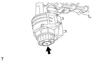
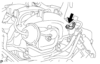
Remove the oil filter drain plug.
-
Text in Illustration *1 Cap *2 Valve *3 Pipe *4 O-Ring *5 Hose Install the pipe to the oil filter cap.
Note
If the O-ring is removed with the drain plug, install the O-ring together with the pipe.
Tech Tips
Use a container to catch the draining oil.
-
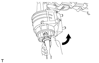
Check that oil is drained from the oil filter. Then disconnect the pipe and remove the O-ring as shown in the illustration.
-
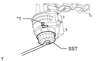
Text in Illustration *1 Oil Filter Bracket Clip Using SST, remove the oil filter cap.
- SST
- 09228-06501
Note
Do not remove the oil filter bracket clip.
-
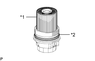
Text in Illustration *1 Oil Filter Element *2 O-Ring Remove the oil filter element and O-ring from the oil filter cap.
Note
Be sure to remove the cap O-ring by hand, without using any tools, to prevent damage to the cap O-ring groove.
-
-
REMOVE ENGINE OIL LEVEL DIPSTICK GUIDE
-
Отсоедините зажим жгута проводов.
-
Снимите щуп проверки уровня масла.
-
Выверните болт и снимите трубку щупа проверки уровня масла.
-
Снимите кольцевое уплотнение с трубки щупа.
-
-
REMOVE OIL PRESSURE SENDER GAUGE ASSEMBLY
-
Disconnect the sender gauge connector.
-
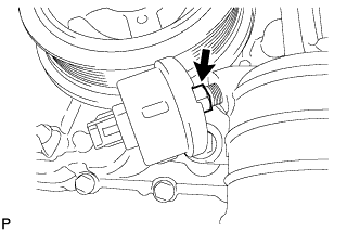
Remove the oil pressure sender gauge.
-
-
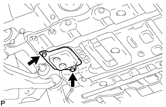
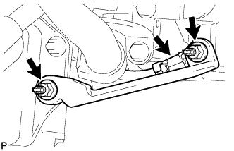
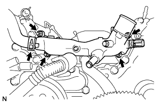
REMOVE NO. 2 WATER BY-PASS PIPE SUB-ASSEMBLY
-
Remove the 3 bolts.
-
Disconnect the 4 hoses and remove the water by-pass pipe.
-
-
REMOVE NO. 1 OIL COOLER BRACKET
-
Remove the 2 nuts and bracket.
-
Disconnect the ground wire from the cylinder block.
-
-
REMOVE OIL FILTER BRACKET
-
Text in Illustration *1 Pipe *2 Hose Connect a hose with an inside diameter of 15 mm (0.591 in.) to the pipe.
-
Remove the oil filter drain plug.
-
Text in Illustration *1 Cap *2 Valve *3 Pipe *4 O-Ring *5 Hose Install the pipe to the oil filter cap.
Note
If the O-ring is removed with the drain plug, install the O-ring together with the pipe.
Tech Tips
Use a container to catch the draining oil.
-
Check that oil is drained from the oil filter. Then disconnect the pipe and remove the O-ring as shown in the illustration.
-
Text in Illustration *1 Oil Filter Bracket Clip Using SST, remove the oil filter cap.
- SST
- 09228-06501
Note
Do not remove the oil filter bracket clip.
-
Text in Illustration *1 Oil Filter Element *2 O-Ring Remove the oil filter element and O-ring from the oil filter cap.
Note
Be sure to remove the cap O-ring by hand, without using any tools, to prevent damage to the cap O-ring groove.
-
-
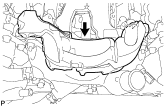
REMOVE INTAKE MANIFOLD
-
Отсоедините шланг вентиляции картера от трубки вентиляции картера правой и левой крышек головки блока цилиндров.
-
Отсоедините два перепускных шланга охлаждающей жидкости.
-
Отсоедините разъем корпуса дроссельной заслонки.
-
Отсоедините шланг вентиляции картера № 1.
-
Отсоедините разъем электровакуумного клапана продувки (VSV).
-
Отсоедините шланг продувки от электровакуумного клапана продувки.
-
Отсоедините разъем электровакуумного клапана (для ACIS).
-

Снимите крышку двигателя № 1 в сборе.
-
Снимите крышку двигателя № 3.
-
Отсоедините 3 зажима жгута проводов от 3 кронштейнов жгута проводов.
-
Выверните болт и снимите кронштейн жгута проводов с впускного коллектора.
-
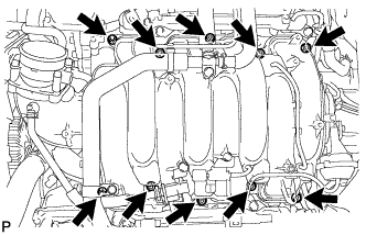
Отверните 2 гайки, выверните 8 болтов и снимите впускной коллектор и 2 прокладки.
-
-
DISCONNECT VANE PUMP ASSEMBLY
-
Remove the 2 bolts and disconnect the vane pump.
-
-
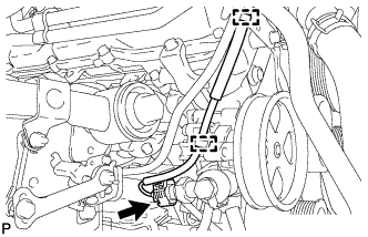
DISCONNECT OIL COOLER PIPE ASSEMBLY
-
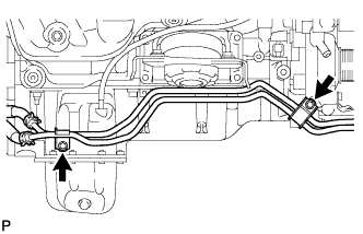
Выверните 2 болта и отсоедините трубку масляного радиатора.
-
-
REMOVE GENERATOR ASSEMBLY
-
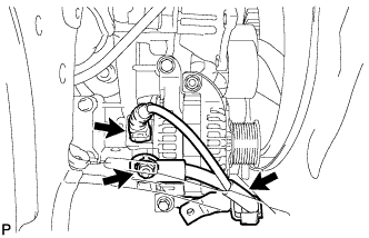
Disconnect the generator connector.
-
Open the terminal cap.
-
Remove the nut and disconnect the generator wire.
-
Remove the bolt and disconnect the wire harness bracket from the generator.
-
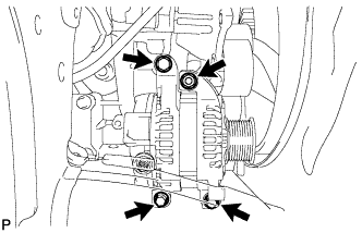
Remove the 3 bolts, nut and generator.
-
Remove the stud bolt.
-
-
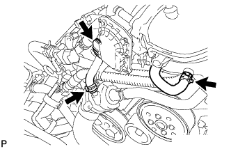
REMOVE NO. 1 WATER BY-PASS HOSE
-
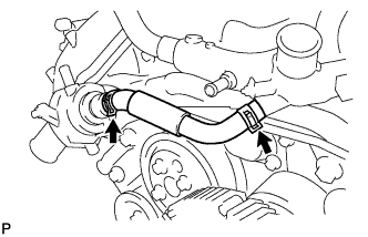
Remove the No. 1 water by-pass hose by disconnecting the hose from the water inlet housing and front water by-pass joint.
-
-
REMOVE WATER BY-PASS PIPE SUB-ASSEMBLY
-
Disconnect the 2 hoses.
-
Remove the 2 bolts and water by-pass pipe.
-
-
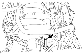
REMOVE FRONT WATER BY-PASS JOINT
-
Disconnect the No. 2 water by-pass hose from the water by-pass joint.
-
Remove the 4 nuts, water by-pass joint and 2 gaskets.
-
-
REMOVE NO. 2 ENGINE COVER
-
REMOVE NO. 1 ENGINE COVER
-
REMOVE WATER INLET HOUSING
-
Remove the 3 bolts, water inlet housing and gasket.
-
-
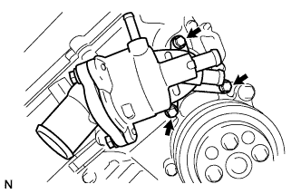
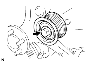
REMOVE WATER PUMP PULLEY
-
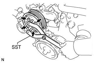
Using SST, hold the water pump pulley.
- SST
- 09960-10010 ( 09962-01000, 09963-01000 )
-
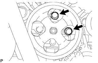
Remove the 4 bolts and water pump pulley.
-
-
REMOVE NO. 1 IDLER PULLEY SUB-ASSEMBLY
-
Remove the bolt and idler pulley.
-
-
REMOVE FLUID COUPLING BRACKET
-
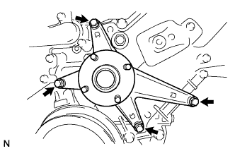
Remove the 4 bolts and fluid coupling bracket.
-
-
REMOVE V-RIBBED BELT TENSIONER ASSEMBLY
-
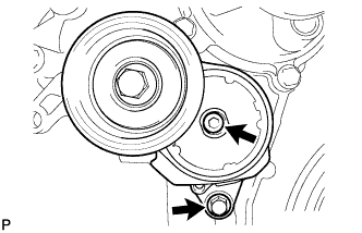
Remove the standard bolt, 6 mm hexagon wrench bolt and belt tensioner.
-
-
REMOVE IGNITION COIL ASSEMBLY
-
Remove the 8 bolts and 8 ignition coils.
-
-
REMOVE CYLINDER HEAD COVER SUB-ASSEMBLY LH
-
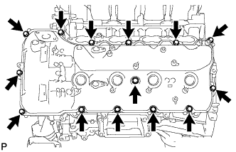
Remove the 14 bolts, seal washer, cylinder head cover and gasket.
Tech Tips
Make sure the removed parts are returned to the same places they were removed from.
-
Remove the 5 gaskets from the camshaft bearing caps (No. 2, No. 3).
-
-
REMOVE CYLINDER HEAD COVER SUB-ASSEMBLY RH
-
Remove the bolt and noise filter.
-
Remove the 14 bolts, seal washer, cylinder head cover and gasket.
Tech Tips
Make sure the removed parts are returned to the same places they were removed from.
-
Remove the 5 gaskets from the camshaft bearing caps (No. 1, No. 3).
-
-
REMOVE SPARK PLUG TUBE GASKET
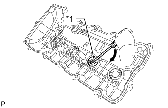
Text in Illustration *1 Tape 
Pry
-
Bend the 4 ventilation baffle plate claws on the cylinder head cover to an angle of 90° or more.
-
Using a screwdriver, pry out the gaskets.
Note
-
Be careful not to damage the cylinder head cover.
-
Be careful not to damage the gasket when removing it, as the removed gasket needs to be used when installing a new one.
Tech Tips
Tape the screwdriver tip before use.
-
-
-
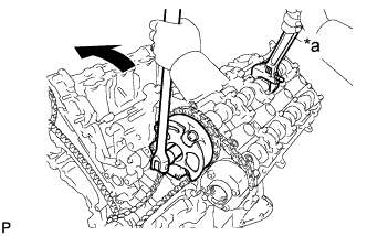
REMOVE CRANKSHAFT PULLEY
-
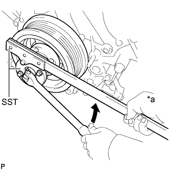
Text in Illustration *a Hold Turn Using SST, loosen the crankshaft pulley set bolt until 2 or 3 threads are engaged.
- SST
- 09213-70011
- 09330-00021
-
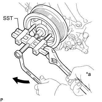
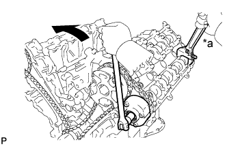
Text in Illustration *a Hold Turn Using the pulley set bolt and SST, remove the crankshaft pulley.
- SST
- 09950-50013 ( 09951-05010, 09952-05010, 09953-05010, 09954-05011 )
-
-
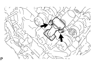
DISCONNECT WIRE HARNESS CLAMP BRACKET
-
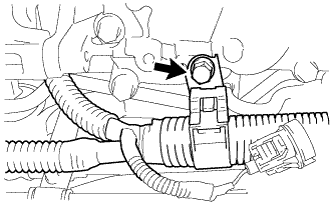
Remove the bolt and disconnect the bracket.
-
-
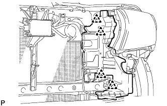
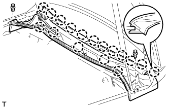
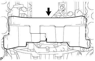
REMOVE TIMING CHAIN COVER SUB-ASSEMBLY
-
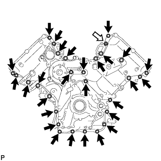
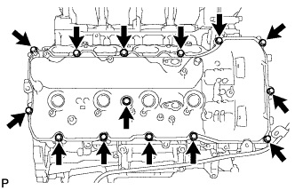
Remove the 28 bolts and nut shown in the illustration.
Text in Illustration Bolt 
Nut -
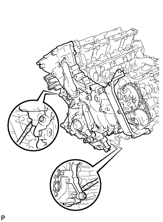
Remove the timing chain cover by prying between the timing chain cover and cylinder head or cylinder block with a screwdriver as shown in the illustration.
Note
Be careful not to damage the contact surfaces of the cylinder head, cylinder block and chain cover.
Tech Tips
Tape the screwdriver tip before use.
-
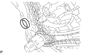
Remove the oil pump gasket from the cylinder block.
-
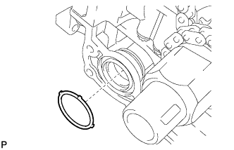
Remove the O-ring from the oil pan.
-
-
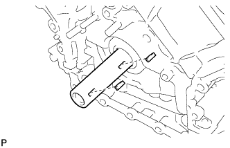
REMOVE WATER INLET PIPE
-
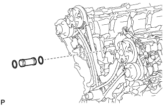
Remove the water inlet pipe.
-
Remove the 2 O-rings from the water inlet pipe.
-
-
SET NO. 1 CYLINDER TO TDC/COMPRESSION
-
Temporarily install the crankshaft pulley bolt.
-
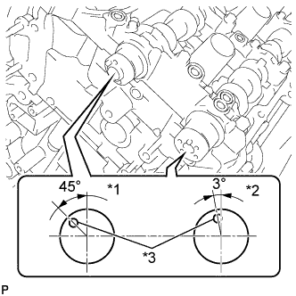
Rotate the crankshaft clockwise so that the timing marks on the crankshaft timing sprocket and camshaft timing gears are as shown in the illustration.
Tech Tips
If the timing marks do not align, rotate the crankshaft clockwise again and align the timing marks.
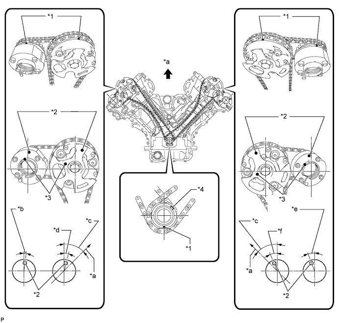
Text in Illustration *1 Timing Mark *2 Timing Mark Position *3 Knock Pin Position *4 Key *a Toward Ceiling *b Approximately 2° *c Approximately 45° *d Approximately 16° *e Approximately 18° *f Approximately 32°
-
-
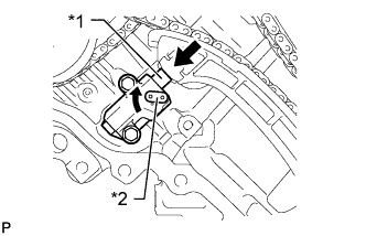
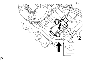
REMOVE NO. 1 CHAIN TENSIONER ASSEMBLY LH
-
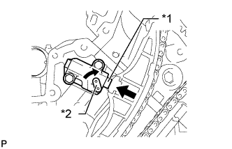
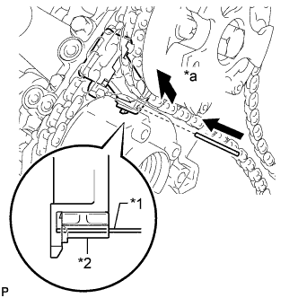
Text in Illustration *1 Plunger *2 Stopper Plate Move the stopper plate clockwise to release the lock, and push the plunger deep into the tensioner.
-
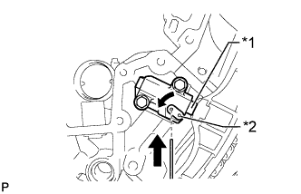
Text in Illustration *1 Plunger *2 Stopper Plate Move the stopper plate counterclockwise to set the lock, and insert a hexagon wrench into the stopper plate hole.
-
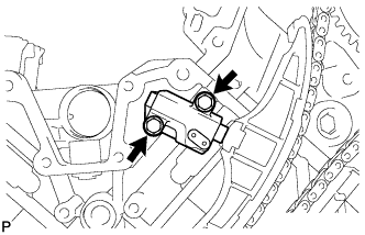
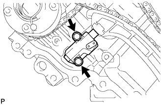
Remove the 2 bolts, chain tensioner and gasket.
-
-
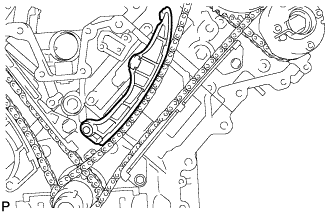
REMOVE NO. 1 CHAIN TENSIONER SLIPPER LH
-
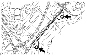
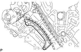
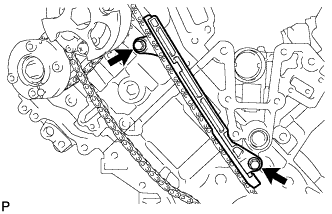
REMOVE NO. 1 CHAIN VIBRATION DAMPER LH
-
Remove the 2 bolts and chain vibration damper.
-
-
REMOVE NO. 1 CHAIN SUB-ASSEMBLY LH
-
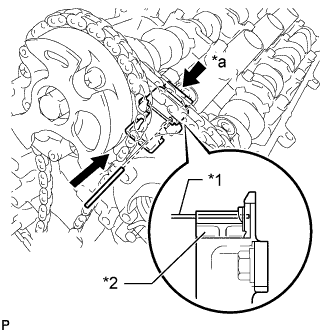
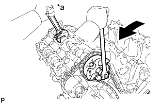
Text in Illustration *1 Pin *2 Plunger *a Push While pushing down the No. 3 chain tensioner, insert a pin of 1.0 mm (0.0394 in.) into the hole to fix it in place.
-
Text in Illustration *a Hold Turn Hold the hexagonal portion of the camshaft with a wrench and loosen the bolt.
Note
-
Be careful not to damage the cylinder head with the wrench.
-
Do not disassemble the camshaft timing gear.
-
-
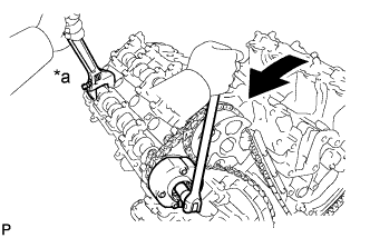
Text in Illustration *a Hold Turn Hold the hexagonal portion of the camshaft with a wrench and loosen the bolt.
Note
Be careful not to damage the cylinder head with the wrench.
-
Remove the 2 bolts. Then with the No. 1 and No. 2 chains still connected to the gears, remove the camshaft timing gear, camshaft timing exhaust gear and crankshaft timing sprocket LH.
-
Remove the No. 1 and No. 2 chains from the gears.
-
-
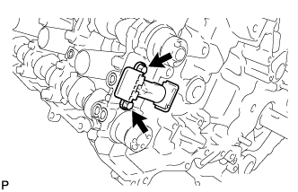
REMOVE NO. 3 CHAIN TENSIONER ASSEMBLY
-
Remove the 2 bolts and chain tensioner.
-
-
REMOVE NO. 1 CHAIN TENSIONER ASSEMBLY RH
-
Text in Illustration *1 Plunger *2 Stopper Plate Move the stopper plate clockwise to release the lock, and push the plunger deep into the tensioner.
-
Text in Illustration *1 Plunger *2 Stopper Plate Move the stopper plate counterclockwise to set the lock, and insert a hexagon wrench into the stopper plate hole.
-
Remove the 2 bolts and chain tensioner.
-
-
REMOVE NO. 1 CHAIN TENSIONER SLIPPER RH
-
REMOVE NO. 1 CHAIN VIBRATION DAMPER RH
-
Remove the 2 bolts and vibration damper.
-
-
REMOVE NO. 1 CHAIN SUB-ASSEMBLY RH
-
Text in Illustration *1 Pin *2 Plunger *a Push While raising up the No. 2 chain tensioner, insert a pin of 1.0 mm (0.0394 in.) into the hole to fix it in place.
-
Text in Illustration *a Hold Turn Hold the hexagonal portion of the camshaft with a wrench and loosen the bolt.
Note
-
Be careful not to damage the cylinder head with the wrench.
-
Do not disassemble the camshaft timing gear.
-
-
Text in Illustration *a Hold Turn Hold the hexagonal portion of the camshaft with a wrench and loosen the bolt.
Note
Be careful not to damage the cylinder head with the wrench.
-
Remove the 2 bolts. Then with the No. 1 and No. 2 chains still connected to the gears, remove the camshaft timing gear, camshaft timing exhaust gear and crankshaft timing sprocket RH.
-
Remove the No. 1 and No. 2 chains from the gears.
-
-
REMOVE NO. 2 CHAIN TENSIONER ASSEMBLY
-
Remove the 2 bolts and chain tensioner.
-
-
REMOVE CRANKSHAFT TIMING GEAR KEY
-
Using a screwdriver, remove the 2 timing gear keys from the crankshaft.
-
-
REMOVE CAMSHAFT BEARING CAP LH
-
Text in Illustration *1 IN *2 EX *3 Knock Pin Make sure that the knock pin of the camshaft is positioned as shown in the illustration.
-
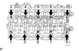
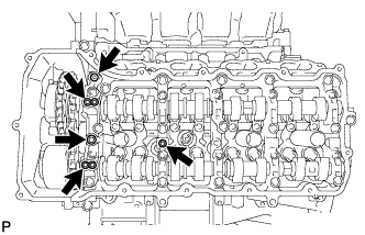
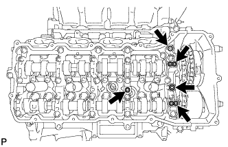
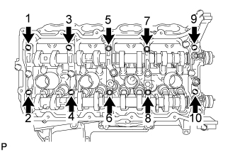
Uniformly loosen and remove the 10 bearing cap bolts in the sequence shown in the illustration.
-
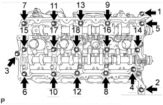
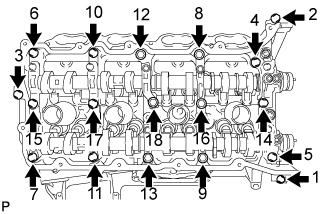
Uniformly loosen and remove the 18 bearing cap bolts in the sequence shown in the illustration.
Note
Uniformly loosen the bolts while keeping the camshaft level.
-
Remove the 6 bearing caps.
Tech Tips
Arrange the removed parts in the correct order.
-
Remove the No. 3 and No. 4 camshafts.
-
-
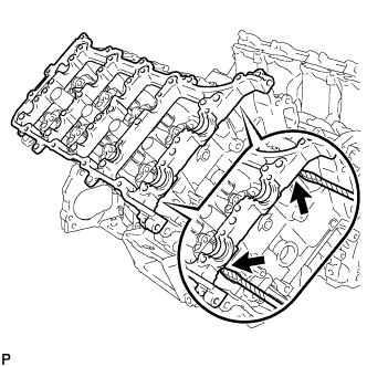
REMOVE CAMSHAFT HOUSING SUB-ASSEMBLY LH
-
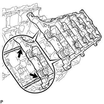
Remove the camshaft housing by prying between the cylinder head and camshaft housing with a screwdriver.
Note
Be careful not to damage the contact surfaces of the cylinder head and camshaft housing.
Tech Tips
Tape the screwdriver tip before use.
-
-
REMOVE CAMSHAFT BEARING CAP RH
-
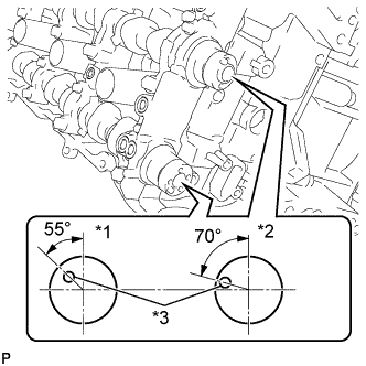
Text in Illustration *1 EX *2 IN *3 Knock Pin Make sure that the knock pin of the camshaft is positioned as shown in the illustration.
-
Uniformly loosen and remove the 10 bearing cap bolts in the sequence shown in the illustration.
-
Uniformly loosen and remove the 18 bearing cap bolts in the sequence shown in the illustration.
Note
Uniformly loosen the bolts while keeping the camshaft level.
-
Remove the 6 bearing caps.
Tech Tips
Arrange the removed parts in the correct order.
-
Remove the No. 1 and No. 2 camshafts.
-
-
REMOVE CAMSHAFT HOUSING SUB-ASSEMBLY RH
-
Remove the camshaft housing by prying between the cylinder head and camshaft housing with a screwdriver.
Note
Be careful not to damage the contact surfaces of the cylinder head and camshaft housing.
Tech Tips
Tape the screwdriver tip before use.
-