- Click here
INSPECT REMOTE CONTROL SWITCH ASSEMBLY
-
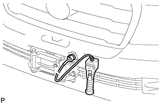
Connect the remote control switch connector.
-
Turn the engine switch on (IG) and check that the power indicator light illuminates.
-
Press the remote control switch, and check that the winch operates.
Note:Be careful not to tighten or strain the winch wire.
-
Turn the engine switch off.
-
- Click here
REMOVE FRONT FENDER SPLASH SHIELD SUB-ASSEMBLY LH
-
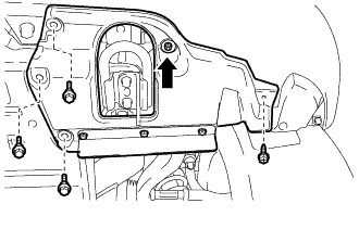
Remove the 3 bolts and screw.
-
Turn the clip indicated by the arrow in the illustration to remove the front fender splash shield sub-assembly LH.
-
- Click here
REMOVE FRONT FENDER SPLASH SHIELD SUB-ASSEMBLY RH
-
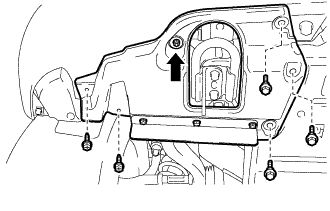
Remove the 3 bolts and 2 screws.
-
Turn the clip indicated by the arrow in the illustration to remove the front fender splash shield sub-assembly RH.
-
- Click here
REMOVE UPPER RADIATOR SUPPORT SEAL
- Click here
REMOVE FRONT BUMPER WINCH COVER SUB-ASSEMBLY
-
Detach the 2 claws.
-
Detach the 3 guides and remove front bumper winch cover sub-assembly.
-
- Click here
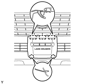
REMOVE RADIATOR GRILLE ASSEMBLY
-

Put protective tape around the radiator grille assembly.
Table 1. Text in Illustration *1 Protective Tape -
Remove the 3 screws.
-
Detach the 2 clips and 8 claws, and remove the radiator grille assembly.
-
w/ Wide View Front Monitor System:
-
Disconnect the connector.
-
-
- Click here
REMOVE FRONT BUMPER COVER
-
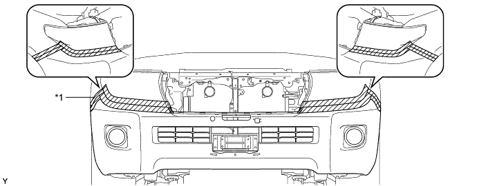
Put protective tape around the bumper cover.
Table 2. Text in Illustration *1 Protective Tape - - -
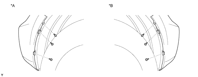
Using a T30 "TORX" socket, remove the 6 screws.
Table 3. Text in Illustration *A LH Side *B RH Side -
Remove the 3 clips, 4 screws and 4 bolts.
-
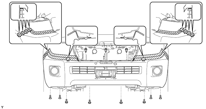
Detach the 10 claws.
-
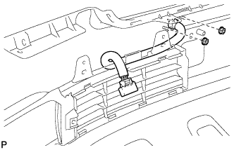
Disconnect the winch control wire connector and remove the front bumper cover.
-
w/ Fog Light:
Disconnect the No. 4 engine room wire connector and remove the front bumper cover.
-
- Click here
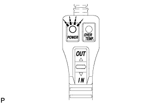
INSPECT OVERHEAT TEMPERATURE INDICATOR
-
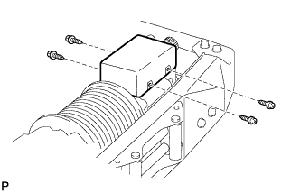
Remove the 4 screws and cover.
-
Disconnect the motor relay connector.
-
Remove the 2 nuts.
-
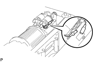
Pull the bumper side winch control wire out of the bumper.
-
Connect the bumper side winch control wire connector to the vehicle side winch control wire connector.
-
Connect the bumper side winch control wire connector to the winch control switch connector.
-
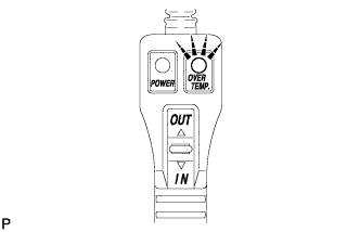
Turn the engine switch on (IG) and check that the overheat temperature indicator light illuminates and the buzzer sounds.
-
Turn the engine switch off.
-
Disconnect the bumper side winch control wire connector from the winch control switch connector.
-
Disconnect the bumper side winch control wire connector from the vehicle side winch control wire connector.
-
Pass the bumper side winch control wire through the bumper.
-
Install the 2 nuts.
-
Connect the motor relay connector.
-
Install the cover with the 4 screws.
-
- Click here
INSTALL FRONT BUMPER COVER
-
w/ Fog Light:
Connect the No. 4 engine room wire connector.
-
Connect the winch control wire connector and attach the 10 claws to install the front bumper cover.
-
Install the 3 clips, 4 screws and 4 bolts.
-
Using a T30 "TORX" socket, install the 6 screws.
-
- Click here
INSTALL RADIATOR GRILLE ASSEMBLY
-
w/ Wide View Front Monitor System:
-
Connect the connector.
-
-
Attach the 2 clips and 8 claws to install the radiator grille assembly.
-
Install the 3 screws.
-
- Click here
INSTALL FRONT BUMPER WINCH COVER SUB-ASSEMBLY
- Click here
INSTALL UPPER RADIATOR SUPPORT SEAL
-
for Gasoline Engine:
Install the upper radiator support seal (Click here).
-
for Diesel Engine:
Install the upper radiator support seal (See page ).
-
- Click here
INSTALL FRONT FENDER SPLASH SHIELD SUB-ASSEMBLY LH
-
Push in the clip to install the front fender splash shield sub-assembly LH.
-
Install the 3 bolts and screw.
-
- Click here
INSTALL FRONT FENDER SPLASH SHIELD SUB-ASSEMBLY RH
-
Push in the clip to install the front fender splash shield sub-assembly RH.
-
Install the 3 bolts and 2 screws.
-