WINCH UNIT INSPECTION

-
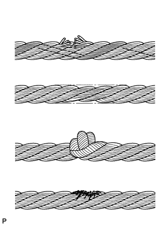
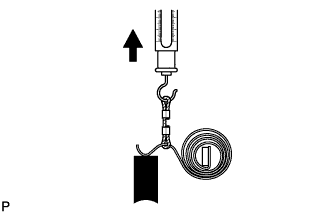
INSPECT WINCH WIRE
-
Inspect the wire for the following damage: 1) areas where several strands are severed; 2) areas where the diameter is less than 7.5 mm (0.295 in.); 3) kinks; 4) corrosion; and 5) fraying.
If the wire is damaged, replace it with a new one.
-
-
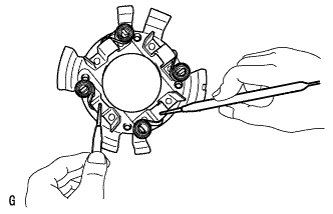
INSPECT WINCH MOTOR ARMATURE SUB-ASSEMBLY
-
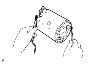
Inspect the commutator for a shot circuit.
-
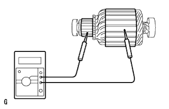
Measure the resistance according to the value(s) in the table below.
Standard Resistance Tester Connection Condition Specified Condition Commutator - Armature core Always 10 kΩ or higher If the result is not as specified, replace the armature sub-assembly.
-
-
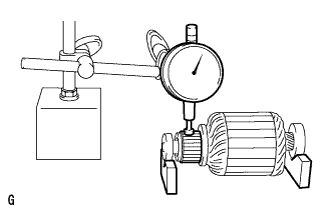
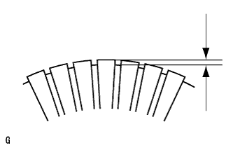
Using a dial indicator, measure the circle runout of the commutator.
Standard runout 0.05 mm (0.0020 in.) or less Maximum runout 0.2 mm (0.008 in.) If the circle runout is more than the maximum, correct it with a lathe.
-
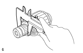
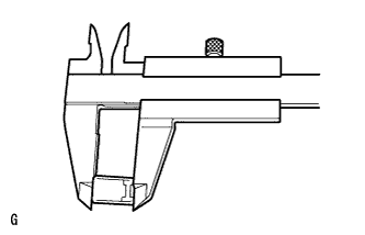
Using a vernier caliper, measure the diameter of the commutator.
Standard diameter 43 mm (1.69 in.) Minimum diameter 41 mm (1.61 in.) If the diameter of the commutator is less than the minimum, replace the armature.
-
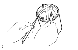
Check that the undercut depth is clean and free of foreign particles. Then smooth off the edge and measure the undercut depth.
Standard undercut depth 0.5 to 0.8 mm (0.020 to 0.031 in.) Minimum undercut depth 0.2 mm (0.008 in.) If the undercut depth is less that the minimum, correct it with a hacksaw blade.
-
-
INSPECT WINCH MOTOR YOKE SUB-ASSEMBLY
-
Inspect for an open circuit.
-
Measure the resistance according to the value(s) in the table below.
Standard Resistance Tester Connection Condition Specified Condition Lead wire - Field coil brush lead Always 10 kΩ or higher If the result is not as specified, replace the winch motor yoke sub-assembly.
-
-
Inspect the shunt coil for an open circuit.
-
Measure the resistance according to the value(s) in the table below.
Standard Resistance Tester Connection Condition Specified Condition Field coil brush lead - Field frame Always Below 1 Ω If the result is not as specified, replace the winch motor yoke sub-assembly.
-
-
-
INSPECT WINCH MOTOR BRUSH
-
Using a vernier caliper, measure the length of the brush.
Standard length 22 mm (0.87 in.) Minimum length 15 mm (0.59 in.) If the brush length is less than the minimum, replace the brush.
-
-
INSPECT WINCH MOTOR BRUSH SPRING
-
Using a pull scale, measure the installed load of the brush spring.
Standard installed load 16 to 20 N (1.6 to 2.0 kgf 3.6 to 4.4 lbf) Tech Tips
Take the pull scale reading at the very instant the brush spring separates from the brush.
-
-
INSPECT WINCH MOTOR BRUSH HOLDER ASSEMBLY
-
Inspect for an open circuit.
-
Measure the resistance according to the value(s) in the table below.
Standard Resistance Tester Connection Condition Specified Condition Positive (+) brush holder - Negative (-) brush holder Always Below 1 Ω If the result is not specified, replace the brush holder assembly.
-
-
-
INSPECT NO. 1 WINCH MOTOR ARMATURE BEARING
-
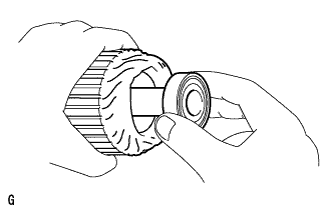
Turn each bearing by hand while applying inward force.
If the bearing sticks or resists, replace it.
-