REMOTE CONTROL SWITCH INSPECTION

-
INSPECT OVERHEAT TEMPERATURE INDICATOR
-
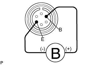
Apply battery voltage and check operation of the remote control switch, as shown in the table below.
OK Measurement Condition Specified Condition Battery positive (+) → Terminal B
Battery negative (-) → Terminal E
Overheat temperature indicator light illuminates and buzzer sounds If the result is not as specified, replace the remote control switch assembly.
-
-
INSPECT REMOTE CONTROL SWITCH CIRCUIT
-
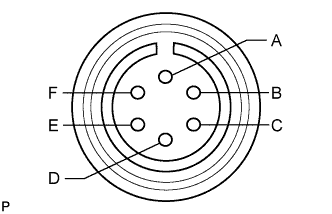
Measure the resistance according to the value(s) in the table below.
Standard Resistance Tester Connection Switch Condition Specified Condition A - B*1
B - C
B - E*2
Not pushed Below 1 Ω B - D Pushed to IN Below 1 Ω B - F Pushed to OUT Below 1 Ω Tech Tips
-
*1: Connect the positive (+) lead of the ohmmeter to terminal B and the negative (-) lead to terminal A.
-
*2: Connect the positive (+) lead of the ohmmeter to terminal E and the negative (-) lead to terminal B.
If the result is not as specified, replace the remote control switch assembly.
-
-