REAR BUMPER (for Standard) DISASSEMBLY

-
REMOVE NO. 2 FRAME WIRE
-
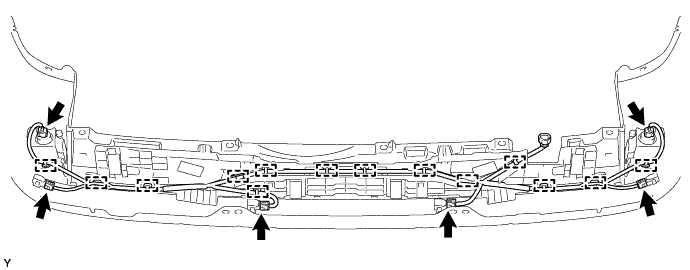
w/ TOYOTA Parking Assist-sensor System, w/o Rear Fog Light:
Remove the No. 2 frame wire.
-
Disconnect the 4 connectors.
-
Detach the 12 clamps and remove the No. 2 frame wire.
-
-
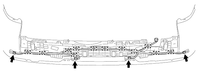
w/ TOYOTA Parking Assist-sensor System, w/ Rear Fog Light:
Remove the No. 2 frame wire.
-
Disconnect the 6 connectors.
-
Detach the 14 clamps and remove the No. 2 frame wire.
-
-
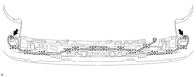
w/o TOYOTA Parking Assist-sensor System, w/ Rear Fog Light:
Remove the No. 2 frame wire.
-
Disconnect the 2 connectors.
-
Detach the 13 clamps and remove the No. 2 frame wire.
-
-
-
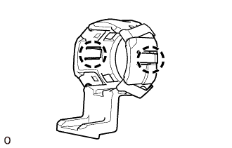
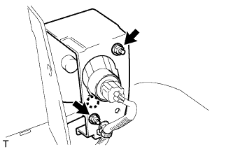
REMOVE NO. 1 ULTRASONIC SENSOR (w/ TOYOTA Parking Assist-sensor System)
-
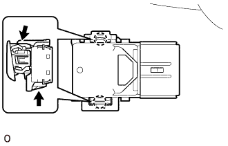
Detach the 2 claws and remove the No. 1 ultrasonic sensor.
Tech Tips
-
Use the same procedure for all No. 1 ultrasonic sensors.
-
The illustration shows the No. 1 ultrasonic sensor for the RH corner and back sensor LH and RH. The installation position of the No. 1 ultrasonic sensor for the LH corner is on the opposite side.
-
-
-
REMOVE NO. 1 ULTRASONIC SENSOR RETAINER (w/ TOYOTA Parking Assist-sensor System)
-
Detach the 2 claws and remove the No. 1 ultrasonic sensor retainer from the rear bumper cover.
Tech Tips
-
Use the same procedure to remove the No. 1 ultrasonic sensor retainer on the other side.
-
The illustration shows the No. 1 ultrasonic sensor retainer for the RH corner. The vertical orientation of the No. 1 ultrasonic sensor retainers for the LH corner is opposite that of the image shown in the illustration.
-
-
-
REMOVE NO. 2 ULTRASONIC SENSOR RETAINER (w/ TOYOTA Parking Assist-sensor System)
-
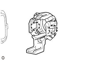
Detach the 2 claws and remove the No. 2 ultrasonic sensor retainer from the rear bumper cover.
Tech Tips
Use the same procedure to remove the No. 2 ultrasonic sensor retainer on the other side.
-
-
REMOVE REAR BUMPER ENERGY ABSORBER
-
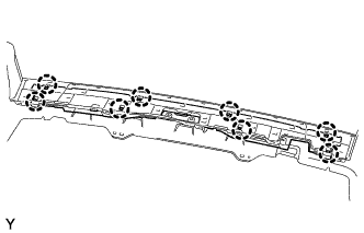
Detach the 8 claws and remove the rear bumper energy absorber.
-
-
REMOVE REFLEX REFLECTOR ASSEMBLY LH (w/o Rear Fog Light)
-
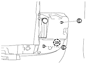
Remove the 2 nuts.
-
Detach the claw and remove the reflex reflector assembly LH.
-
-
REMOVE REFLEX REFLECTOR ASSEMBLY RH (w/o Rear Fog Light)
Tech Tips
Use the same procedure described for the LH side.
-
REMOVE REAR FOG LIGHT ASSEMBLY LH (w/ Rear Fog Light)
-
Remove the 2 nuts.
-
Disconnect the connectors.
-
Detach the claw and remove the fog light.
-
-
REMOVE REAR FOG LIGHT ASSEMBLY RH (w/ Rear Fog Light)
Tech Tips
Use the same procedure described for the LH side.
-
REMOVE REAR NO. 2 BUMPER SIDE BRACKET (w/ Tire Carrier)
-
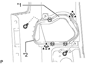
Text in Illustration *1 Rear No. 2 Bumper Side Bracket *2 Rear No. 3 Bumper Side Bracket Remove the 2 screws.
-
Detach the 3 claws and 2 clips, and remove the rear No. 2 bumper side bracket and rear No. 3 bumper side bracket.
-