LIGHTING SYSTEM Engine Switch Illumination Circuit
DESCRIPTION
The engine switch illumination is controlled by the main body ECU. The operation and condition of this control are described below (Light control switch is OFF).
| Operation | Condition |
|---|---|
| Fade in | When any of the following conditions is met, the engine switch illumination fades in.
|
| Fade out immediately | When either of the following conditions is met, the engine switch illumination fades out.
|
| Illuminate for approximately 15 seconds, and then fade out | All the doors are closed when the engine switch is off. |
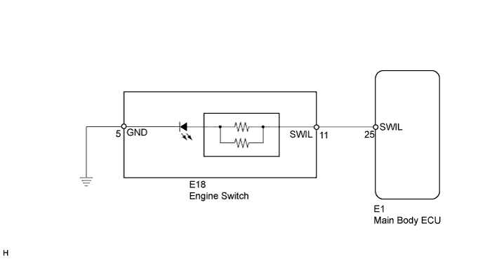
WIRING DIAGRAM
INSPECTION PROCEDURE
PROCEDURE
-
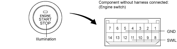
INSPECT ENGINE SWITCH
-
Remove the engine switch Click here.
-
Apply battery voltage to the engine switch.
-
Check that the illumination comes on.
OK Measurement Condition Specified Condition Battery positive (+) → Terminal 11 (SWIL)
Battery negative (-) → Terminal 5 (GND)
Engine switch illumination comes on
NG 
REPLACE ENGINE SWITCH Click here
OK 
-
-
CHECK HARNESS AND CONNECTOR (ENGINE SWITCH - MAIN BODY ECU AND BODY GROUND)
-
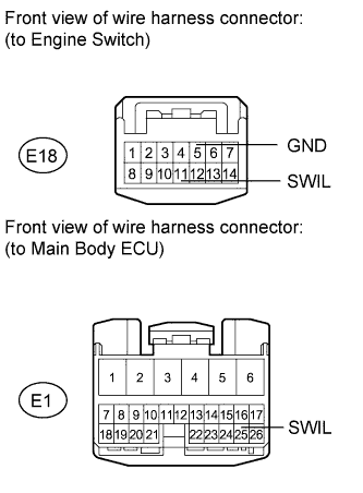
Disconnect the E1 ECU connector.
-
Disconnect the E18 engine switch connector.
-
Measure the resistance according to the value(s) in the table below.
Standard Resistance Tester Connection Condition Specified Condition E1-11 (SWIL) - E1-25 (SWIL) Always Below 1 Ω E18-5 (GND) - Body ground E1-11 (SWIL) - Body ground Always 10 kΩ or higher
NG
REPAIR OR REPLACE HARNESS OR CONNECTOR
OK 
REPLACE MAIN BODY ECU
-