LIGHTING SYSTEM Door Courtesy Light Circuit
DESCRIPTION
The door courtesy light turns on when the door is opened and turns off when closed.
WIRING DIAGRAM
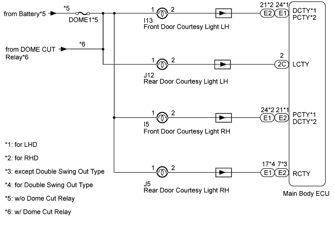
INSPECTION PROCEDURE
PROCEDURE
-
CHECK OPERATION OF DOOR COURTESY LIGHT
-
When a door is opened, check that the following lights do not illuminate.
Result Result Proceed to All door courtesy light does not illuminate A Front door courtesy light LH does not illuminate B Front door courtesy light RH does not illuminate C Rear door courtesy light LH does not illuminate D Rear door courtesy light RH does not illuminate E
B 
INSPECT DOOR COURTESY LIGHT (FRONT DOOR LH) Click here
C
INSPECT DOOR COURTESY LIGHT (FRONT DOOR RH) Click here
D
INSPECT COURTESY LIGHT (REAR DOOR LH) Click here
E
INSPECT DOOR COURTESY LIGHT (REAR DOOR RH) Click here
A 
-
-
INSPECT FUSE (DOME1)
-
Remove the DOME1 fuse from the engine room junction block.
-
Measure the resistance according to the value(s) in the table below.
Standard Resistance Tester Connection Condition Specified Condition DOME1 fuse Always Below 1 Ω
NG 
REPLACE FUSE
OK
-
-
CHECK HARNESS AND CONNECTOR (DOOR COURTESY LIGHT - BODY GROUND)
-
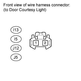
Disconnect the I13, I5, J12 and J5 ECU connectors.
-
Measure the voltage according to the value(s) in the table below.
Standard Voltage Tester Connection Switch Condition Specified Condition I13-1 - Body ground Always 11 to 14 V J12-1 - Body ground I5-1 - Body ground J5-1 - Body ground
NG
REPAIR OR REPLACE HARNESS OR CONNECTOR
OK 
PROCEED TO NEXT INSPECTION PROCEDURE SHOWN IN PROBLEM SYMPTOMS TABLE Click here
-
-
INSPECT DOOR COURTESY LIGHT (FRONT DOOR LH)
-
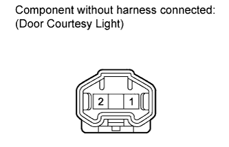
Remove the door courtesy light connector.
-
Check that the door courtesy light comes on.
OK Measurement Condition Specified Condition Battery positive (+) - Terminal 2
Battery positive (-) - Terminal 1
Light illumination
NG
CHECK HARNESS AND CONNECTOR (MAIN BODY ECU - BODY GROUND) Click here
OK
END
-
-
CHECK HARNESS AND CONNECTOR (MAIN BODY ECU - BODY GROUND)
-
Remove the main body ECU.
-
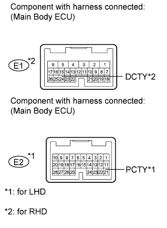
for LHD:
-
Measure the voltage according to the value(s) in the table below.
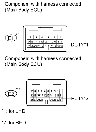
Standard Voltage Tester Connection Condition Specified Condition E1-24 (DCTY) - Body ground Always 11 to 14V
-
-
for RHD:
-
Measure the voltage according to the value(s) in the table below.
Standard Voltage Tester Connection Condition Specified Condition E2-21 (PCTY) - Body ground Always 11 to 14V
-
NG
REPAIR OR REPLACE HARNESS OR CONNECTOR
OK
REPLACE MAIN BODY ECU
-
-
INSPECT DOOR COURTESY LIGHT (FRONT DOOR RH)
-
Remove the door courtesy light connector.
-
Check that the door courtesy light comes on.
OK Measurement Condition Specified Condition Battery positive (+) - Terminal 2
Battery positive (-) - Terminal 1
Light illumination
NG
CHECK HARNESS AND CONNECTOR (MAIN BODY ECU - BODY GROUND) Click here
OK
END
-
-
CHECK HARNESS AND CONNECTOR (MAIN BODY ECU - BODY GROUND)
-
Remove the main body ECU.
-
for LHD:
-
Measure the voltage according to the value(s) in the table below.
Standard Voltage Tester Connection Condition Specified Condition E2-21 (PCTY) - Body ground Always 11 to 14V
-
-
for RHD:
-
Measure the voltage according to the value(s) in the table below.
Standard Voltage Tester Connection Condition Specified Condition E1-24 (DCTY) - Body ground Always 11 to 14V
-
NG
REPAIR OR REPLACE HARNESS OR CONNECTOR
OK
REPLACE MAIN BODY ECU
-
-
INSPECT COURTESY LIGHT (REAR DOOR LH)
-
Remove the door courtesy light connector.
-
Check that the door courtesy light comes on.
OK Measurement Condition Specified Condition Battery positive (+) - Terminal 2
Battery positive (-) - Terminal 1
Light illumination
NG
CHECK HARNESS AND CONNECTOR (MAIN BODY ECU - BODY GROUND) Click here
OK
END
-
-
CHECK HARNESS AND CONNECTOR (MAIN BODY ECU - BODY GROUND)
-
Remove the main body ECU.
-
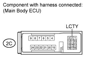
Measure the voltage according to the value(s) in the table below.
Standard Voltage Tester Connection Condition Specified Condition 2C-2 (LCTY) - Body ground Always 11 to 14V
NG
REPAIR OR REPLACE HARNESS OR CONNECTOR
OK
REPLACE MAIN BODY ECU
-
-
INSPECT DOOR COURTESY LIGHT (REAR DOOR RH)
-
Remove the door courtesy light connector.
-
Check that the door courtesy light comes on.
OK Measurement Condition Specified Condition Battery positive (+) - Terminal 2
Battery positive (-) - Terminal 1
Light illumination
NG
CHECK HARNESS AND CONNECTOR (MAIN BODY ECU - BODY GROUND) Click here
OK
END
-
-
CHECK HARNESS AND CONNECTOR (MAIN BODY ECU - BODY GROUND)
-
Remove the main body ECU.
-
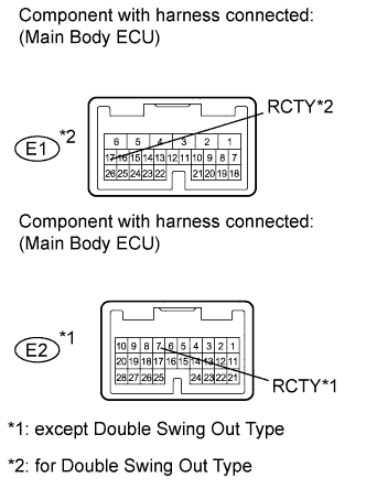
except Double Swing Out Type:
-
Measure the voltage according to the value(s) in the table below.
Standard Voltage Tester Connection Condition Specified Condition E2-7 (RCTY) - Body ground Always 11 to 14V
-
-
for Double Swing Out Type:
-
Measure the voltage according to the value(s) in the table below.
Standard Voltage Tester Connection Condition Specified Condition E1-17 (RCTY) - Body ground Always 11 to 14V
-
NG
REPAIR OR REPLACE HARNESS OR CONNECTOR
OK
REPLACE MAIN BODY ECU
-