LIGHTING SYSTEM Turn Signal Light Circuit
DESCRIPTION
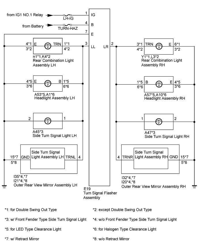
The turn signal flasher receives a turn signal switch signal from the headlight dimmer switch, and illuminates the front turn signal light, side turn signal light and rear turn signal light.
WIRING DIAGRAM
INSPECTION PROCEDURE
Note
Inspect the fuses and bulbs for circuits related to this system before performing the following inspection procedure.
PROCEDURE
-
CHECK TURN SIGNAL LIGHT FUNCTION
-
Check that the turn signal lights blink.
Result Result Proceed to All turn signal lights do not blink A LH side turn signal light does not blink B RH side turn signal light does not blink C
B 
CHECK HARNESS AND CONNECTOR (REAR COMBINATION LIGHT ASSEMBLY LH - TURN SIGNAL FLASHER ASSEMBLY AND BODY GROUND) Click here
C
CHECK HARNESS AND CONNECTOR (REAR COMBINATION LIGHT ASSEMBLY RH - TURN SIGNAL FLASHER ASSEMBLY AND BODY GROUND) Click here
A 
-
-
CHECK HARNESS AND CONNECTOR (TURN SIGNAL FLASHER ASSEMBLY - BATTERY AND BODY GROUND)
-
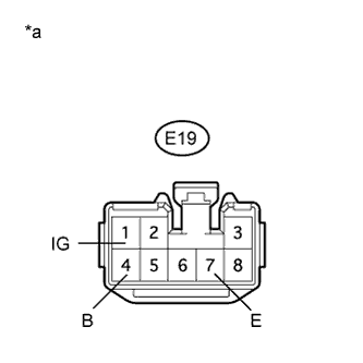
Text in Illustration *a Front view of wire harness connector
(to Turn Signal Flasher Assembly)
Disconnect the turn signal flasher connector.
-
Measure the voltage according to the value(s) in the table below.
Standard Voltage Tester Connection Condition Specified Condition E19-1 (IG) - Body ground Ignition switch ON 11 to 14 V Ignition switch off Below 1 V E19-4 (B) - Body ground Always 11 to 14 V -
Measure the resistance according to the value(s) in the table below.
Standard Resistance Tester Connection Condition Specified Condition E19-7 (E) - Body ground Always Below 1 Ω
NG 
REPAIR OR REPLACE HARNESS OR CONNECTOR
OK 
PROCEED TO NEXT SUSPECTED AREA SHOWN IN PROBLEM SYMPTOMS TABLE Click here
-
-
CHECK HARNESS AND CONNECTOR (REAR COMBINATION LIGHT ASSEMBLY LH - TURN SIGNAL FLASHER ASSEMBLY AND BODY GROUND)
-
Disconnect the E19 turn signal flasher connector.
-
for Double Swing Out Type:
-
Disconnect the n1 rear combination light LH connector.
-
Measure the resistance according to the value(s) in the table below.
Standard Resistance Tester Connection Condition Specified Condition n1-1 (TRN) - E19-3 (LL) Always Below 1 Ω n1-4 (E) - Body ground n1-1 (TRN) - Body ground Always 10 kΩ or higher
-
-
except Double Swing Out Type:
-
Disconnect the K4 rear combination light LH connector.
-
Measure the resistance according to the value(s) in the table below.
Standard Resistance Tester Connection Condition Specified Condition K4-4 (TRN) - E19-3 (LL) Always Below 1 Ω K4-3 (E) - Body ground K4-4 (TRN) - Body ground Always 10 kΩ or higher
-
NG
REPAIR OR REPLACE HARNESS OR CONNECTOR
OK
PROCEED TO NEXT SUSPECTED AREA SHOWN IN PROBLEM SYMPTOMS TABLE Click here
-
-
CHECK HARNESS AND CONNECTOR (REAR COMBINATION LIGHT ASSEMBLY RH - TURN SIGNAL FLASHER ASSEMBLY AND BODY GROUND)
-
Disconnect the E19 turn signal flasher connector.
-
for Double Swing Out Type:
-
Disconnect the Y1 rear combination light RH connector.
-
Measure the resistance according to the value(s) in the table below.
Standard Resistance Tester Connection Condition Specified Condition Y1-3 (TRN) - E19-2 (LR) Always Below 1 Ω Y1-6 (E) - Body ground Y1-3 (TRN) - Body ground Always 10 kΩ or higher
-
-
except Double Swing Out Type:
-
Disconnect the L3 rear combination light RH connector.
-
Measure the resistance according to the value(s) in the table below.
Standard Resistance Tester Connection Condition Specified Condition L3-4 (TRN) - E19-2 (LR) Always Below 1 Ω L3-3 (E) - Body ground L3-4 (TRN) - Body ground Always 10 kΩ or higher
-
NG
REPAIR OR REPLACE HARNESS OR CONNECTOR
OK
PROCEED TO NEXT SUSPECTED AREA SHOWN IN PROBLEM SYMPTOMS TABLE Click here
-