LIGHTING SYSTEM TERMINALS OF ECU

-
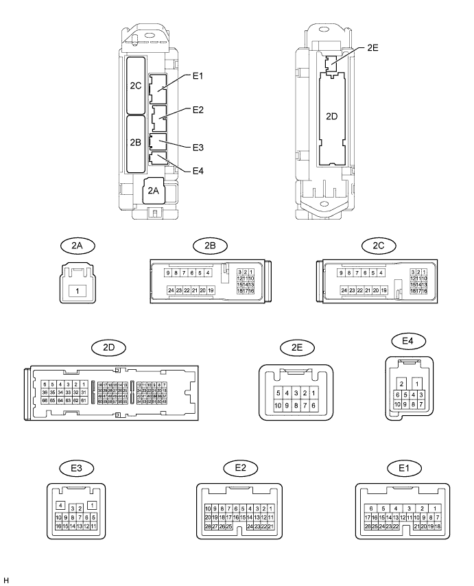
CHECK MAIN BODY ECU (COWL SIDE JUNCTION BLOCK LH)
-
Disconnect the E1, E2, E3, 2A, 2B, 2C, and 2D ECU connectors.
-
Measure the voltage and resistance according to the value(s) in the table below.
Terminal No. (Symbol) Wiring Color Terminal Description Condition Specified Condition 2A-1 - Body ground B - Body ground Battery power supply Always 11 to 14 V 2D-62 (GND2) - Body ground W-B - Body ground Body ground Always Below 1 Ω 2D-62 (GND1) - Body ground*1 W-B - Body ground Body ground Always Below 1 Ω E3-1 (GND3) - Body ground BR - Body ground Body ground Always Below 1 Ω E1-24 (DCTY) - Body ground*2 L - Body ground Front door courtesy light switch LH signal Front door LH open Below 1 Ω E1-24 (DCTY) - Body ground*2 L - Body ground Front door courtesy light switch LH signal Front door LH closed 10 kΩ or higher E1-24 (DCTY) - Body ground*3 P - Body ground Front door courtesy light switch LH signal Front door LH open Below 1 Ω E1-24 (DCTY) - Body ground*3 P - Body ground Front door courtesy light switch LH signal Front door LH closed 10 kΩ or higher E2-21 (PCTY) - Body ground*2 Y - Body ground*4
P - Body ground*5
Front door courtesy light switch RH signal Front door RH open Below 1 Ω E2-21 (PCTY) - Body ground*2 Y - Body ground*4
P - Body ground*5
Front door courtesy light switch RH signal Front door RH closed 10 kΩ or higher E2-21 (PCTY) - Body ground*3 L - Body ground Front door courtesy light switch RH signal Front door RH open Below 1 Ω E2-21 (PCTY) - Body ground*3 L - Body ground Front door courtesy light switch RH signal Front door RH closed 10 kΩ or higher 2C-2 (LCTY) - Body ground W - Body ground Rear door courtesy light switch LH signal Rear door LH open Below 1 Ω 2C-2 (LCTY) - Body ground W - Body ground Rear door courtesy light switch LH signal Rear door LH closed 10 kΩ or higher E2-7 (RCTY) - Body ground*4 G - Body ground Rear door courtesy light switch RH signal Rear door RH open Below 1 Ω E2-7 (RCTY) - Body ground*4 G - Body ground Rear door courtesy light switch RH signal Rear door RH closed 10 kΩ or higher E1-17 (RCTY) - Body ground*1 G - Body ground Rear door courtesy light switch RH signal Rear door RH open Below 1 Ω E1-17 (RCTY) - Body ground*1 G - Body ground Rear door courtesy light switch RH signal Rear door RH closed 10 kΩ or higher E2-25 (BCTY) - Body ground W - Body ground Back door courtesy light switch signal Back door open Below 1 Ω E2-25 (BCTY) - Body ground W - Body ground Back door courtesy light switch signal Back door closed 10 kΩ or higher E1-23 (TAIL) - Body ground V - Body ground Light control switch TAIL signal Light control switch tail Below 1 Ω E1-23 (TAIL) - Body ground V - Body ground Light control switch TAIL signal Light control switch except tail 10 kΩ or higher E2-17 (HEAD) - Body ground R- Body ground Light control switch HEAD signal Light control switch head Below 1 Ω E2-17 (HEAD) - Body ground R - Body ground Light control switch HEAD signal Light control switch except head 10 kΩ or higher E1-21 (A) - Body ground G - Body ground Light control switch AUTO signal Light control switch auto Below 1 Ω E1-21 (A) - Body ground G - Body ground Light control switch AUTO signal Light control switch except auto 10 kΩ or higher E2-28 (FFOG) - Body ground R - Body ground Front fog light switch signal Front fog light switch on Below 1 Ω E2-28 (FFOG) - Body ground R - Body ground Front fog light switch signal Front fog light switch off 10 kΩ or higher E2-9 (RFOG) - Body ground R - Body ground Rear fog light switch signal Rear fog light switch on Below 1 Ω E2-9 (RFOG) - Body ground R - Body ground Rear fog light switch signal Rear fog light switch off 10 kΩ or higher 2D-13 (HU) - Body ground R - Body ground Dimmer switch high signal Dimmer switch high Below 1 Ω 2D-13 (HU) - Body ground R - Body ground Dimmer switch high signal Dimmer switch except high or flash 10 kΩ or higher E1-13 (HF) - Body ground GR - Body ground Dimmer switch flash signal Dimmer switch flash Below 1 Ω E1-13 (HF) - Body ground GR - Body ground Dimmer switch flash signal Dimmer switch except flash 10 kΩ or higher 2D-51 (ILE) - Body ground G - Body ground Interior light signal Map light on Below 1 Ω 2D-51 (ILE) - Body ground G - Body ground Interior light signal Map light off 10 kΩ or higher Tech Tips
*1: w/o Entry and Start System
*2: for LHD
*3: for RHD
*4: Model code: GRJ200L-GNANKC, URJ202L-GNTEKC
*5: Model code except: GRJ200L-GNANKC, URJ202L-GNTEKC
-
Reconnect the E1, E2, E3, 2A, 2B, 2C, and 2D ECU connectors.
-
Measure the voltage according to the value(s) in the table below.
Terminal No. (Symbol) Wiring Color Terminal Description Condition Specified Condition E1-4 (FFGO) - Body ground R - Body ground Front fog light signal Light control switch tail,
front fog light switch on
Below 1 V E1-4 (FFGO) - Body ground R - Body ground Front fog light signal Light control switch tail,
front fog light switch off
11 to 14 V E2-8 (DRLE) - Body ground R - Body ground Daytime running light signal Daytime running light on Below 1 V E2-8 (DRLE) - Body ground R - Body ground Daytime running light signal Daytime running light off 11 to 14 V E2-15 (DIM) - Body ground*1 L - Body ground Headlight high beam signal Light control switch head,
dimmer switch high
Below 1 V E2-15 (DIM) - Body ground*1 L - Body ground Headlight high beam signal Light control switch head,
dimmer switch except high
11 to 14 V E3-14 (RFGO) - Body ground R - Body ground Rear fog light signal Light control switch tail,
rear fog light switch off
Below 1 V E3-14 (RFGO) - Body ground R - Body ground Rear fog light signal Light control switch tail,
rear fog light switch off
11 to 14 V 2B-18 (HRLY) - Body ground L - Body ground Headlight low beam signal Light control switch head,
dimmer switch low
Below 1 V 2B-18 (HRLY) - Body ground L - Body ground Headlight low beam signal Light control switch head,
dimmer switch except low
11 to 14 V 2B-16 (DIM) - Body ground*2 LG - Body ground Headlight high beam signal Light control switch head,
dimmer switch high
Below 1 V 2B-16 (DIM) - Body ground*2 LG - Body ground Headlight high beam signal Light control switch head,
dimmer switch except high
11 to 14 V 2B-22 (STP) - Body ground R - Body ground Stop light switch signal Brake pedal depressed 11 to 14 V 2B-22 (STP) - Body ground R - Body ground Stop light switch signal Brake pedal released Below 1 V 2D-29 (DOMR) - Body ground*3 R - Body ground Battery save system (interior light auto cut function) signal Battery save system (interior light auto cut function) operating 11 to 14 V 2D-29 (DOMR) - Body ground*3 R - Body ground Battery save system (interior light auto cut function) signal Battery save system (interior light auto cut function) not operating Below 1 V
-
*1: except Double Swing Out Type
-
*2: for Double Swing Out Type
-
*3: w/ Dome Cut Relay
-
-
-
CHECK HEADLIGHT LEVELING ECU ASSEMBLY (w/ Static Headlight Auto Leveling)

-
Disconnect the E109 headlight leveling ECU connector.
-
Measure the voltage and resistance according to the value(s) in the table below.
Terminal No. (Symbol) Wiring Color Terminal Description Condition Specified Condition E109-1 (IG) - Body ground R - Body ground Ignition power supply Ignition switch off Below 1 V Ignition switch ON 11 to 14 V E109-9 (E1) - Body ground W-B - Body ground Ground Always Below 1 Ω If the result is not as specified, there may be a malfunction on the wire harness side.
-
Reconnect the E109 headlight leveling ECU connector.
-
Measure the resistance and voltage according to the value(s) in the table below.
Terminal No. (Symbol) Wiring Color Terminal Description Condition Specified Condition E109-3 (HDLP) - E109-9 (E1) L - W-B Low beam headlight signal input Low beam headlights on Below 1 V Low beam headlights off 11 to 14 V E109-5 (INIT) - E109-9 (E1) LG - W-B Initialization signal input Terminal LVL and terminal CG of DLC3 connected Below 1 V Terminal LVL and terminal CG of DLC3 not connected 4.5 to 5.5 V E109-6 (WNG) - E109-9 (E1) L - W-B Warning indicator drive output Warning indicator on Below 1 V Warning indicator off 11 to 14 V E109-10 (RH+) - E109-9 (E1) G - W-B Headlight leveling motor RH power supply Ignition switch off Below 1 V Ignition switch ON 11 to 14 V E109-11 (LH+) - E109-9 (E1) R - W-B Headlight leveling motor LH power supply Ignition switch off Below 1 V Ignition switch ON 11 to 14 V E109-12 (SBR) - E109-21 (SGR) L - P Rear height control sensor power supply Ignition switch off Below 1 V Ignition switch ON 4.75 to 5.25 V E109-16 (SPDR) - E109-9 (E1) V - W-B Vehicle speed signal input Vehicle is driven at approximately 20 km/h (12 mph) Pulse generation
(See waveform 1)
E109-17 (RHT) - E109-9 (E1) P - W-B Headlight leveling motor RH operation signal input With low beam headlights on, vehicle height not changed Below 1 V With low beam headlights on, vehicle height changed and maintained for more than 3 seconds 1.0 to 14.4 V E109-18 (LHT) - E109-9 (E1) G - W-B Headlight leveling motor LH operation signal input With low beam headlights on, vehicle height not changed Below 1 V With low beam headlights on, vehicle height changed and maintained for more than 3 seconds 1.0 to 14.4 V E109-19 (SHRL) - E109-21 (SGR) Y - P*1
SB - P*2
Rear height control sensor signal input Ignition switch off Below 1 V Ignition switch ON 0.5 to 4.5 V E109-21 (SGR) - E109-9 (E1) P - W-B Rear height control sensor ground Always Below 1 Ω E109-23 (RH-) - E109-9 (E1) BR - W-B Headlight leveling motor RH ground Always Below 1 Ω E109-24 (LH-) - E109-9 (E1) V - W-B Headlight leveling motor LH ground Always Below 1 Ω
-
*1: Model code: GRJ200L-GNANKC, URJ202L-GNTEKC
-
*2: Model code except: GRJ200L-GNANKC, URJ202L-GNTEKC
-
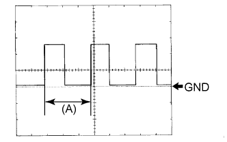
Waveform 1
Item Content Terminal No. (Symbol) E109-16 (SPDR) - E109-9 (E1) Tool setting 5 V/DIV., 20 ms./DIV. Condition Vehicle is driven at approximately 20 km/h (12 mph) Tech Tips
When the system is functioning normally, one wheel revolution generates 4 pulses. As the vehicle speed increases, the width indicated by (A) in the illustration narrows.
-
-
-
CHECK HEADLIGHT SWIVEL ECU ASSEMBLY (w/ Dynamic Headlight Auto Leveling)

-
Disconnect the E101 headlight swivel ECU connector.
-
Measure the resistance and voltage according to the value(s) in the table below.
Terminal No. (Symbol) Wiring Color Terminal Description Condition Specified Condition E101-15 (IG) - Body ground R - Body ground Ignition power supply Ignition switch off Below 1 V Ignition switch ON 11 to 14 V E101-22 (E1) - Body ground W-B - Body ground Ground Always Below 1 Ω If the result is not as specified, there may be a malfunction on the wire harness side.
-
Reconnect the E101 headlight swivel ECU connector.
-
Measure the resistance and voltage according to the value(s) in the table below.
Terminal No. (Symbol) Wiring Color Terminal Description Condition Specified Condition E101-3 (LHT) - E101-22 (E1) R - W-B Headlight leveling motor LH power supply Ignition switch off Below 1 V Ignition switch ON 11 to 14 V E101-4 (RHT) - E101-22 (E1) G - W-B Headlight leveling motor RH power supply Ignition switch off Below 1 V Ignition switch ON 11 to 14 V E101-7 (INIT) - E101-22 (E1) LG - W-B Initialization signal Ignition switch ON, terminals LVL and GND of DLC3 connected Below 1 V Ignition switch ON, terminals LVL and GND of DLC3 not connected 4.5 to 5.5 V E101-11 (RH+) - E101-22 (E1) P - W-B Headlight leveling motor RH LIN communication Ignition switch off Below 1 V Ignition switch ON Pulse generation E101-17 (SHFL) - E101-22 (E1)*1 GR - W-B Vehicle height signal Ignition switch off Below 1 V Ignition switch ON Approximately 2.5 V (When vehicle level)
(The value changes according to the vehicle height)
E101-18 (SBR) - E101-22 (E1)*1 L - W-B Vehicle height signal Ignition switch off Below 1 V Ignition switch ON 4.5 to 5.5 V E101-18 (SBR) - E101-21 (SGR)*2 L - P Rear height control sensor LH power supply Ignition switch off Below 1 V Ignition switch ON 4.5 to 5.5 V E101-19 (SHRL) - E101-22 (E1)*1 SB - W-B Vehicle height signal Ignition switch off Below 1 V Ignition switch ON Approximately 2.5 V (When vehicle level)
(The value changes according to the vehicle height)
E101-19 (SHRL) - E101-21 (SGR)*2 SB - P Rear height control sensor LH signal Ignition switch off Below 1 V Ignition switch ON Approximately 2.5 V (When vehicle level)
(The value changes according to the vehicle height)
E101-21 (SGR) - E101-22 (E1)*1 P - W-B Vehicle height signal Always Below 1 Ω E101-21 (SGR) - E101-22 (E1)*2 P - W-B Rear height control sensor LH ground Always Below 1 Ω E101-27 (LH-) - E101-22 (E1) V - W-B Headlight leveling motor LH ground Always Below 1 Ω E101-28 (RH-) - E101-22 (E1) BR - W-B Headlight leveling motor RH ground Always Below 1 Ω E101-30 (LH+) - E101-22 (E1) G - W-B Headlight leveling motor LH LIN communication Ignition switch off Below 1 V Ignition switch ON Pulse generation
-
*1: w/ Active Height Control Suspension
-
*2: w/o Active Height Control Suspension
-
-
-
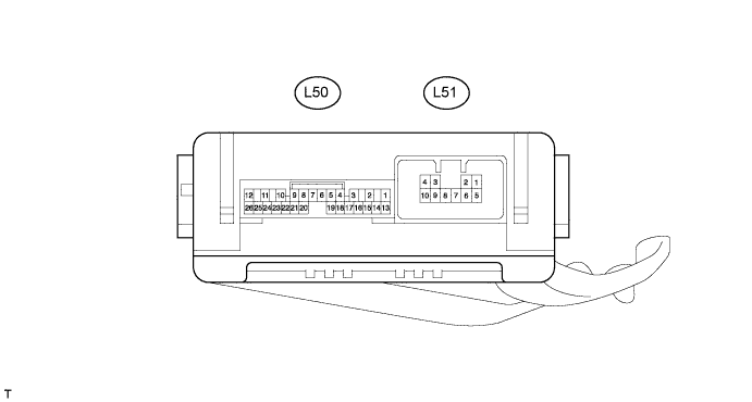
CHECK NO. 2 MAIN BODY ECU (w/ Side Step Light)
-
Disconnect the L50 and L51 ECU connectors.
-
Measure the resistance and voltage according to the value(s) in the table below.
Terminal No. (Symbol) Wiring Color Terminal Description Condition Specified Condition L50-14 (BECU) - Body ground R - Body ground Battery power supply Always 11 to 14 V L50-13 (SIG) - Body ground G - Body ground Ignition power supply Ignition switch off Below 1 V Ignition switch ON 11 to 14 V L50-7 (GND) - Body ground W-B - Body ground Ground Always Below 1 Ω L51-7 (GND) - Body ground W-B - Body ground Ground Always Below 1 Ω
-
If the result is not as specified, there may be a malfunction on the wire harness side.
-
-
Reconnect the L50 and L51 ECU connectors.
-
Measure the voltage according to the value(s) in the table below.
Terminal No. (Symbol) Wiring Color Terminal Description Condition Specified Condition L50-9 (RBD1) - Body ground L - Body ground Step light LH signal Step light LH on Below 1 V Step light LH off 11 to 14 V L50-21 (RBD2) - Body ground L - Body ground Step light RH signal Step light RH on Below 1 V Step light RH off 11 to 14 V
-