LIGHTING SYSTEM Stop Light Circuit
DESCRIPTION
When the stop light switch is turned on, current flows to the stop lights to illuminate them.
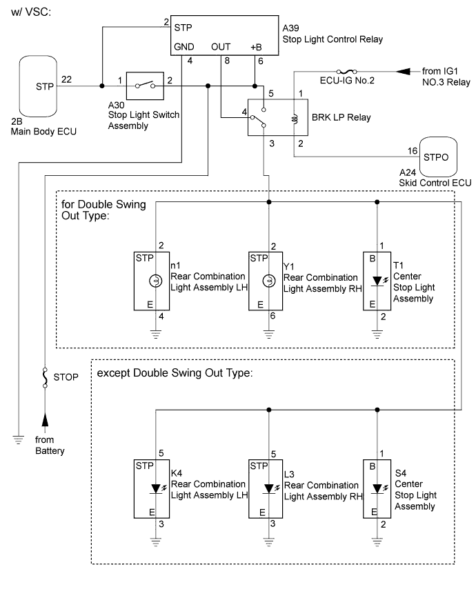
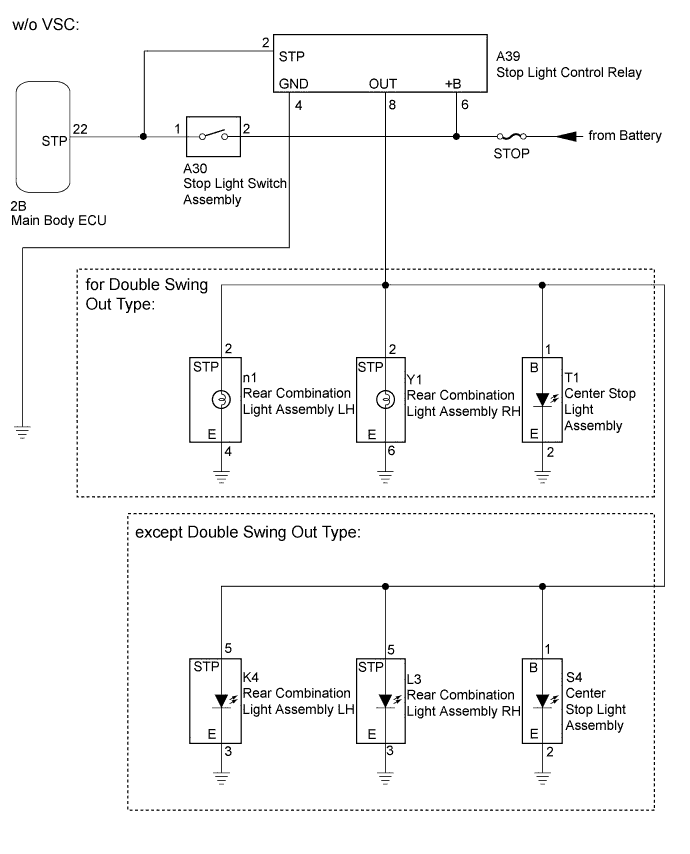
WIRING DIAGRAM
INSPECTION PROCEDURE
PROCEDURE
-
READ VALUE USING INTELLIGENT TESTER (STOP LIGHT SWITCH)
-
Operate the intelligent tester according to the display and select the "Data List".
Main Body Tester Display Measurement Item/Range Normal Condition Diagnostic Note Stop Light SW Stop light switch / ON or OFF ON: Brake pedal depressed
OFF: Brake pedal released
- OK On the intelligent tester screen, each item changes between ON and OFF according to above chart
NG 
INSPECT FUSE (STOP FUSE) Click here
OK 
-
-
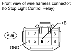
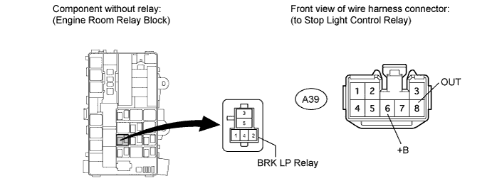
CHECK HARNESS AND CONNECTOR (STOP LIGHT CONTROL RELAY - BATTERY AND BODY GROUND)
-
Disconnect the A39 relay connector.
-
Measure the voltage according to the value(s) in the table below.
Standard Voltage Tester Connection Condition Specified Condition A39-6 (+B) - Body ground Always 11 to 14 V -
Measure the resistance according to the value(s) in the table below.
Standard Resistance Tester Connection Condition Specified Condition A39-4 (GND) - Body ground Always Below 1 Ω
NG 
REPAIR OR REPLACE HARNESS OR CONNECTOR
OK
-
-
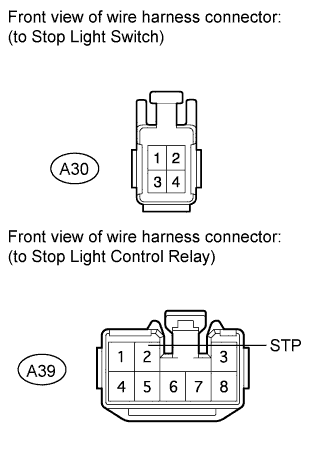
CHECK HARNESS AND CONNECTOR (STOP LIGHT CONTROL RELAY - STOP LIGHT SWITCH)
-
Disconnect the A30 stop light switch connector.
-
Disconnect the A39 relay connector.
-
Measure the resistance according to the value(s) in the table below.
Standard Resistance Tester Connection Condition Specified Condition A30-1 - A39-2 (STP) Always Below 1 Ω A30-1 - Body ground Always 10 kΩ or higher
NG
REPAIR OR REPLACE HARNESS OR CONNECTOR
OK
-
-
CHECK VEHICLE TYPE
-
Check the vehicle type.
Result Result Proceed to w/ VSC A w/o VSC B
B
CHECK VEHICLE TYPE Click here
A
-
-
INSPECT FUSE (ECU-IG No.2 FUSE)
-
Remove the ECU-IG No.2 fuse from the main body ECU.
-
Measure the resistance according to the value(s) in the table below.
Standard Resistance Tester Connection Condition Specified Condition ECU-IG No.2 fuse Always Below 1 Ω
NG
REPLACE FUSE
OK
-
-
INSPECT BRAKE LIGHT RELAY (BRK LP RELAY)
-
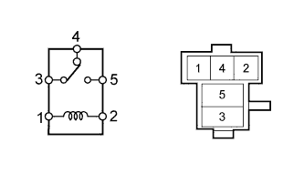
Remove the brake light relay from the engine room relay block.
-
Measure the resistance according to the value(s) in the table below.
Standard Resistance Tester Connection Condition Specified Condition 3 - 5 Battery voltage not applied to terminals 1 and 2 10 kΩ or higher Battery voltage applied to terminals 1 and 2 Below 1 Ω 3 - 4 Battery voltage not applied to terminals 1 and 2 Below 1 Ω Battery voltage applied to terminals 1 and 2 10 kΩ or higher
NG
REPLACE BRAKE LIGHT RELAY (BRK LP RELAY) Click here
OK
-
-
CHECK HARNESS AND CONNECTOR (STOP LIGHT CONTROL RELAY - BRAKE LIGHT RELAY)
-
Remove the brake light relay from the engine room relay block.
-
Disconnect the A39 stop light control relay connector.
-
Measure the resistance according to the value(s) in the table below.
Standard Resistance Tester Connection Condition Specified Condition A39-8 (OUT) - Brake light relay terminal 4 Always Below 1 Ω A39-6 (+B) - Brake light relay terminal 5 A39-8 (OUT) - Body ground Always 10 kΩ or higher A39-6 (+B) - Body ground
NG
REPAIR OR REPLACE HARNESS OR CONNECTOR
OK
-
-
CHECK HARNESS AND CONNECTOR (BRAKE LIGHT RELAY - BATTERY)
-
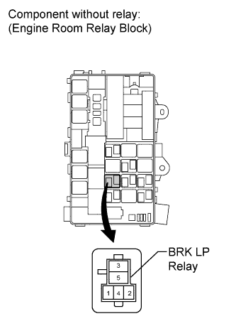
Remove the brake light relay from the engine room relay block.
-
Measure the voltage according to the value(s) in the table below.
Standard Voltage Tester Connection Switch Condition Specified Condition Brake light relay terminal 1 - Body ground Ignition switch ON 11 to 14 V Ignition switch off Below 1 V
NG
REPAIR OR REPLACE HARNESS OR CONNECTOR
OK
-
-
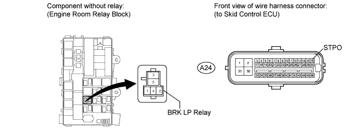
CHECK HARNESS AND CONNECTOR (BRAKE LIGHT RELAY - SKID CONTROL ECU)
-
Remove the brake light relay from the engine room relay block.
-
Disconnect the A24 ECU connector.
-
Measure the resistance according to the value(s) in the table below.
Standard Resistance Tester Connection Condition Specified Condition Brake light relay terminal 2 - A24-16 (STPO) Always Below 1 Ω Brake light relay terminal 2 - Body ground Always 10 kΩ or higher
NG
REPAIR OR REPLACE HARNESS OR CONNECTOR
OK
-
-
CHECK VEHICLE TYPE
-
Check the vehicle type.
Result Result Proceed to for Double Swing Out Type A except Double Swing Out Type B
B
CHECK HARNESS AND CONNECTOR (BRAKE LIGHT RELAY - STOP LIGHT AND BODY GROUND) Click here
A
-
-
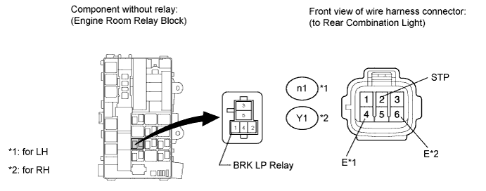
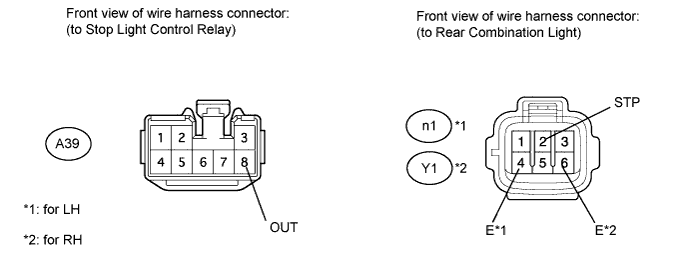
CHECK HARNESS AND CONNECTOR (BRAKE LIGHT RELAY - STOP LIGHT AND BODY GROUND)
-
Remove the brake light relay from the engine room relay block.
-
for LH:
-
Disconnect the n1 light connector.
-
Measure the resistance according to the value(s) in the table below.
Standard Resistance Tester Connection Condition Specified Condition Brake light relay terminal 3 - n1-2 (STP) Always Below 1 Ω n1-4 (E) - Body ground n1-2 (STP) - Body ground Always 10 kΩ or higher
-
-
for RH:
-
Disconnect the Y1 light connector.
-
Measure the resistance according to the value(s) in the table below.
Standard Resistance Tester Connection Condition Specified Condition Brake light relay terminal 3 - Y1-2 (STP) Always Below 1 Ω Y1-6 (E) - Body ground Y1-2 (STP) - Body ground Always 10 kΩ or higher
-
-
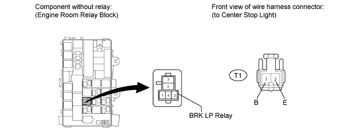
Disconnect the T1 light connector.
-
Measure the resistance according to the value(s) in the table below.
Standard Resistance Tester Connection Condition Specified Condition Brake light relay terminal 3 - T1-1 (B) Always Below 1 Ω T1-2 (E) - Body ground T1-1 (B) - Body ground Always 10 kΩ or higher
NG
REPAIR OR REPLACE HARNESS OR CONNECTOR
OK
-
-
CHECK STOP LIGHT CONTROL RELAY ASSEMBLY
-
Temporarily replace the stop light control relay with a new or normally functioning one.
-
Check the stop light operation.
OK Stop light operation is normal.
NG
REPLACE SKID CONTROL ECU Click here
OK 
REPLACE STOP LIGHT CONTROL RELAY ASSEMBLY Click here
-
-
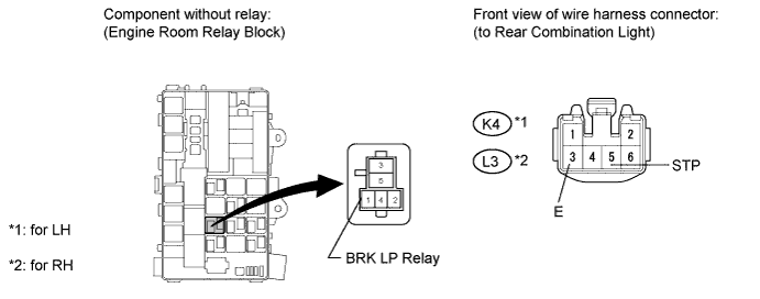
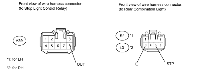
CHECK HARNESS AND CONNECTOR (BRAKE LIGHT RELAY - STOP LIGHT AND BODY GROUND)
-
Remove the brake light relay from the engine room relay block.
-
for LH:
-
Disconnect the K4 light connector.
-
Measure the resistance according to the value(s) in the table below.
Standard Resistance Tester Connection Condition Specified Condition Brake light relay terminal 3 - K4-5 (STP) Always Below 1 Ω K4-3 (E) - Body ground K4-5 (STP) - Body ground Always 10 kΩ or higher
-
-
for RH:
-
Disconnect the L3 light connector.
-
Measure the resistance according to the value(s) in the table below.
Standard Resistance Tester Connection Condition Specified Condition Brake light relay terminal 3 - L3-5 (STP) Always Below 1 Ω L3-3 (E) - Body ground L3-5 (STP) - Body ground Always 10 kΩ or higher
-
-
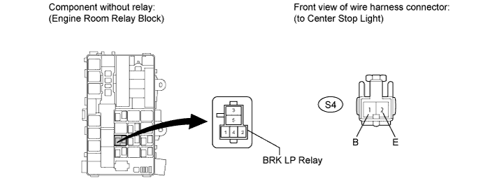
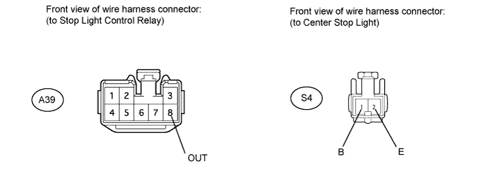
Disconnect the S4 light connector.
-
Measure the resistance according to the value(s) in the table below.
Standard Resistance Tester Connection Condition Specified Condition Brake light relay terminal 3 - S4-1 (B) Always Below 1 Ω S4-2 (E) - Body ground S4-1 (B) - Body ground Always 10 kΩ or higher
NG
REPAIR OR REPLACE HARNESS OR CONNECTOR
OK
-
-
CHECK STOP LIGHT CONTROL RELAY ASSEMBLY
-
Temporarily replace the stop light control relay with a new or normally functioning one.
-
Check the stop light operation.
OK Stop light operation is normal.
NG
REPLACE SKID CONTROL ECU
OK
REPLACE STOP LIGHT CONTROL RELAY ASSEMBLY Click here
-
-
CHECK VEHICLE TYPE
-
Check the vehicle type.
Result Result Proceed to for Double Swing Out Type A except Double Swing Out Type B
B
CHECK HARNESS AND CONNECTOR (STOP LIGHT CONTROL RELAY - STOP LIGHT AND BODY GROUND) Click here
A
-
-
CHECK HARNESS AND CONNECTOR (STOP LIGHT CONTROL RELAY - STOP LIGHT AND BODY GROUND)
-
Disconnect the A39 stop light control relay connector.
-
for LH:
-
Disconnect the n1 light connector.
-
Measure the resistance according to the value(s) in the table below.
Standard Resistance Tester Connection Condition Specified Condition A39-8 (OUT) - n1-2 (STP) Always Below 1 Ω n1-4 (E) - Body ground n1-2 (STP) - Body ground Always 10 kΩ or higher
-
-
for RH:
-
Disconnect the Y1 light connector.
-
Measure the resistance according to the value(s) in the table below.
Standard Resistance Tester Connection Condition Specified Condition A39-8 (OUT) - Y1-2 (STP) Always Below 1 Ω Y1-6 (E) - Body ground Y1-2 (STP) - Body ground Always 10 kΩ or higher
-
-
Disconnect the T1 light connector.

-
Measure the resistance according to the value(s) in the table below.
Standard Resistance Tester Connection Condition Specified Condition A39-8 (OUT) - T1-1 (B) Always Below 1 Ω T1-2 (E) - Body ground T1-1 (B) - Body ground Always 10 kΩ or higher
NG
REPAIR OR REPLACE HARNESS OR CONNECTOR
OK
REPLACE STOP LIGHT CONTROL RELAY ASSEMBLY Click here
-
-
CHECK HARNESS AND CONNECTOR (STOP LIGHT CONTROL RELAY - STOP LIGHT AND BODY GROUND)
-
Disconnect the A39 stop light control relay connector.
-
for LH:
-
Disconnect the K4 light connector.
-
Measure the resistance according to the value(s) in the table below.
Standard Resistance Tester Connection Condition Specified Condition A39-8 (OUT) - K4-5 (STP) Always Below 1 Ω K4-3 (E) - Body ground K4-5 (STP) - Body ground Always 10 kΩ or higher
-
-
for RH:
-
Disconnect the L3 light connector.
-
Measure the resistance according to the value(s) in the table below.
Standard Resistance Tester Connection Condition Specified Condition A39-8 (OUT) - L3-5 (STP) Always Below 1 Ω L3-3 (E) - Body ground L3-5 (STP) - Body ground Always 10 kΩ or higher
-
-
Disconnect the S4 light connector.
-
Measure the resistance according to the value(s) in the table below.
Standard Resistance Tester Connection Condition Specified Condition A39-8 (OUT) - S4-1 (B) Always Below 1 Ω S4-2 (E) - Body ground S4-1 (B) - Body ground Always 10 kΩ or higher
NG
REPAIR OR REPLACE HARNESS OR CONNECTOR
OK
REPLACE STOP LIGHT CONTROL RELAY ASSEMBLY Click here
-
-
INSPECT FUSE (STOP FUSE)
-
Remove the STOP fuse from the engine room relay block.
-
Measure the resistance according to the value(s) in the table below.
Standard Resistance Tester Connection Condition Specified Condition STOP fuse Always Below 1 Ω
NG
REPLACE FUSE
OK
-
-
INSPECT STOP LIGHT SWITCH
-
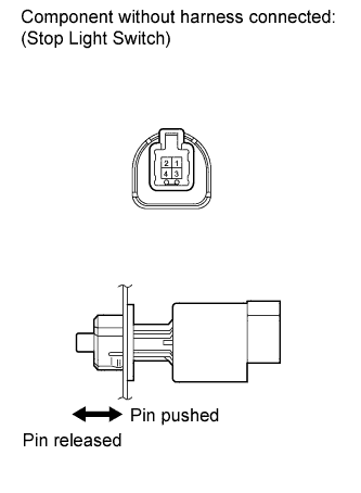
Remove the stop light switch Click here.
-
Measure the resistance according to the value(s) in the table below.
Standard Resistance Tester Connection Switch Condition Specified Condition 1 - 2 Switch pin released Below 1 Ω 1 - 2 Switch pin pushed in 10 kΩ or higher
NG
REPLACE STOP LIGHT SWITCH Click here
OK
-
-
CHECK HARNESS AND CONNECTOR (STOP LIGHT SWITCH - BODY GROUND)
-
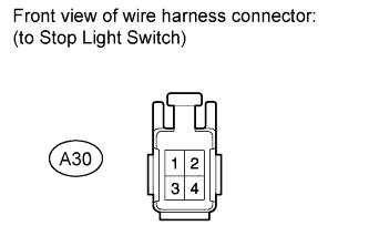
Disconnect the A30 stop light switch connector.
-
Measure the voltage according to the value(s) in the table below.
Standard Voltage Tester Connection Condition Specified Condition A30-2 - Body ground Always 11 to 14 V
NG
REPAIR OR REPLACE HARNESS OR CONNECTOR
OK
-
-
CHECK HARNESS AND CONNECTOR (MAIN BODY ECU - STOP LIGHT SWITCH AND BATTERY)
-
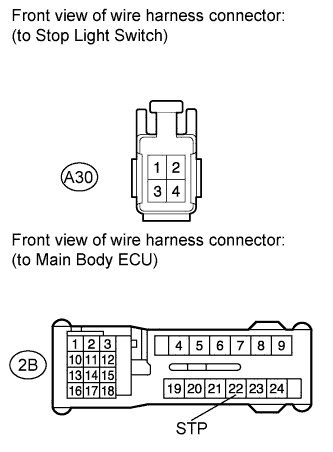
Disconnect the A30 stop light switch connector.
-
Disconnect the 2B ECU connector.
-
Measure the voltage according to the value(s) in the table below.
Standard Voltage Tester Connection Condition Specified Condition 2B-22 (STP) - Body ground Brake pedal depressed 11 to 14 V Brake pedal released Below 1 V -
Measure the resistance according to the value(s) in the table below.
Standard Resistance Tester Connection Condition Specified Condition 2B-22 (STP) - A30-1 Always Below 1 Ω A30-1 - Body ground Always 10 kΩ or higher
NG
REPAIR OR REPLACE HARNESS OR CONNECTOR
OK
REPLACE MAIN BODY ECU
-