LIGHTING SYSTEM Taillight Circuit
DESCRIPTION
The main body ECU receives a light control switch information signal from the headlight dimmer switch, and illuminates the taillights.
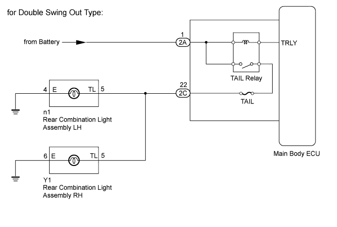
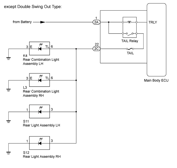
WIRING DIAGRAM
INSPECTION PROCEDURE
PROCEDURE
-
PERFORM ACTIVE TEST USING INTELLIGENT TESTER (TAILLIGHT RELAY)
-
Operate the intelligent tester according to the steps on the display and select "Active Test".
Main Body Tester Display Test Part Control Range Diagnostic Note Taillight Relay Taillight ON or OFF - OK Taillight turns on/turns off.
NG 
INSPECT FUSE (TAIL FUSE) Click here
OK 
PROCEED TO NEXT CIRCUIT INSPECTION SHOWN IN PROBLEM SYMPTOMS TABLE Click here
-
-
INSPECT FUSE (TAIL FUSE)
-
Remove the TAIL fuse from the main body ECU.
-
Measure the resistance according to the value(s) in the table below.
Standard Resistance Tester Connection Condition Specified Condition TAIL fuse Always Below 1 Ω
NG 
REPLACE FUSE
OK 
-
-
CHECK HARNESS AND CONNECTOR (MAIN BODY ECU - BATTERY)
-
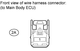
Disconnect the 2A ECU connector.
-
Measure the voltage according to the value(s) in the table below.
Standard Voltage Tester Connection Condition Specified Condition 2A-1 - Body ground Always 11 to 14 V
NG
REPAIR OR REPLACE HARNESS OR CONNECTOR
OK
-
-
CHECK VEHICLE TYPE
-
Check the vehicle type.
Result Result Proceed to for Double Swing Out Type A except Double Swing Out Type B
B
CHECK HARNESS AND CONNECTOR (REAR COMBINATION LIGHT - MAIN BODY ECU AND BODY GROUND) Click here
A
-
-
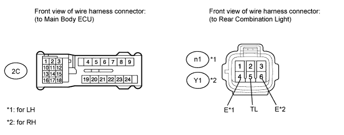
CHECK HARNESS AND CONNECTOR (REAR COMBINATION LIGHT - MAIN BODY ECU AND BODY GROUND)
-
Disconnect the 2C ECU connector.
-
for LH:
-
Disconnect the n1 light connector.
-
Measure the resistance according to the value(s) in the table below.
Standard Resistance Tester Connection Condition Specified Condition 2C-22 - n1-5 (TL) Always Below 1 Ω n1-4 (E) - Body ground n1-5 (TL) - Body ground Always 10 kΩ or higher
-
-
for RH:
-
Disconnect the Y1 light connector.
-
Measure the resistance according to the value(s) in the table below.
Standard Resistance Tester Connection Condition Specified Condition 2C-22 - Y1-5 (TL) Always Below 1 Ω Y1-6 (E) - Body ground Y1-5 (TL) - Body ground Always 10 kΩ or higher
-
NG
REPAIR OR REPLACE HARNESS OR CONNECTOR
OK
REPLACE MAIN BODY ECU
-
-
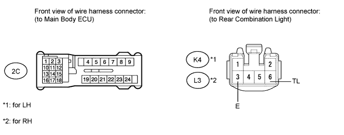
CHECK HARNESS AND CONNECTOR (REAR COMBINATION LIGHT - MAIN BODY ECU AND BODY GROUND)
-
Disconnect the 2C ECU connector.
-
for LH:
-
Disconnect the K4 light connector.
-
Measure the resistance according to the value(s) in the table below.
Standard Resistance Tester Connection Condition Specified Condition 2C-22 - K4-6 (TL) Always Below 1 Ω K4-3 (E) - Body ground K4-6 (TL) - Body ground Always 10 kΩ or higher
-
-
for RH:
-
Disconnect the L3 light connector.
-
Measure the resistance according to the value(s) in the table below.
Standard Resistance Tester Connection Condition Specified Condition 2C-22 - L3-6 (TL) Always Below 1 Ω L3-3 (E) - Body ground L3-6 (TL) - Body ground Always 10 kΩ or higher
-
NG
REPAIR OR REPLACE HARNESS OR CONNECTOR
OK
-
-
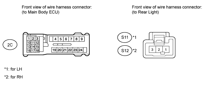
CHECK HARNESS AND CONNECTOR (REAR LIGHT - MAIN BODY ECU AND BODY GROUND)
-
Disconnect the 2C ECU connector.
-
for LH:
-
Disconnect the S11 light connector.
-
Measure the resistance according to the value(s) in the table below.
Standard Resistance Tester Connection Condition Specified Condition 2C-22 - S11-3 Always Below 1 Ω S11-1 - Body ground S11-3 - Body ground Always 10 kΩ or higher
-
-
for RH:
-
Disconnect the S12 light connector.
-
Measure the resistance according to the value(s) in the table below.
Standard Resistance Tester Connection Condition Specified Condition 2C-22 - S12-3 Always Below 1 Ω S12-1 - Body ground S12-3 - Body ground Always 10 kΩ or higher
-
NG
REPAIR OR REPLACE HARNESS OR CONNECTOR
OK
REPLACE MAIN BODY ECU
-