WIPER ECU INSTALLATION

Tech Tips
-
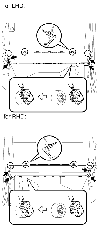
Use the same procedure for LHD and RHD vehicles.
-
The procedure listed below is for LHD vehicles.
-
INSTALL WINDSHIELD WIPER ECU
-
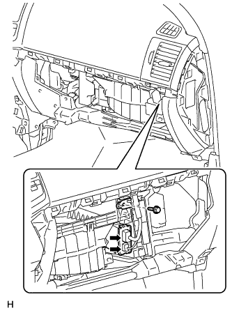
Install the windshield wiper ECU with the screw.
-
Connect the 2 connectors.
-
-
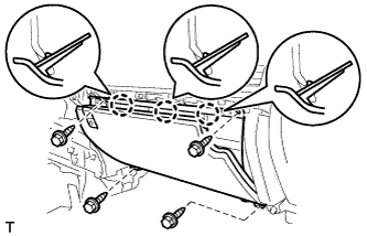
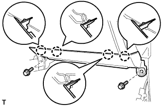
INSTALL LOWER NO. 2 INSTRUMENT PANEL FINISH PANEL
-
Connect the connector.
-
Attach the 3 claws to install the lower No. 2 instrument panel finish panel.
-
Install the 4 bolts.
-
-
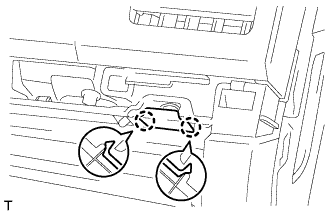
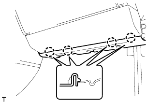
INSTALL INSTRUMENT PANEL BOX DOOR KNOB
-
Attach the 2 claws to install the instrument panel box door knob.
-
-
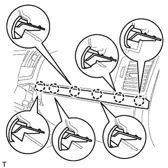
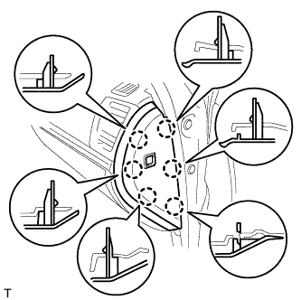
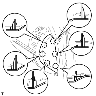
INSTALL NO. 3 INSTRUMENT CLUSTER FINISH PANEL GARNISH
-
Attach the 6 claws to install the No. 3 instrument cluster finish panel garnish.
-
-
INSTALL LOWER INSTRUMENT PANEL (w/o Passenger Side Knee Airbag)
-
Attach the 4 claws to install the lower instrument panel.
-
Install the 2 bolts.
-
-
INSTALL FRONT PASSENGER SIDE KNEE AIRBAG ASSEMBLY (w/ Passenger Side Knee Airbag)
-
Connect the connector.
Note
When handling the airbag connector, take care not to damage the airbag wire harness.
-
Attach the 4 claws to install the front passenger side knee airbag.
-
Install the 4 bolts.
- Torque:
- 10 N*m { 102 kgf*cm, 7 ft.*lbf }
-
-
INSTALL FRONT DOOR SCUFF PLATE RH
Tech Tips
Use the same procedures described for the LH side.
-
INSTALL NO. 2 INSTRUMENT PANEL UNDER COVER SUB-ASSEMBLY (w/ Floor Under Cover)
-
Attach the 4 claws to install the No. 2 instrument panel under cover.
-
-
INSTALL INSTRUMENT SIDE PANEL RH (w/ Airbag Cut Off Switch)
-
Connect the connector.
-
Attach the 6 claws to install the instrument side panel.
-
-
INSTALL INSTRUMENT SIDE PANEL RH (w/o Airbag Cut Off Switch)
-
Attach the 6 claws to install the instrument side panel.
-
-
CONNECT CABLE TO NEGATIVE BATTERY TERMINAL
Note
When disconnecting the cable, some systems need to be initialized after the cable is reconnected Click here.
-
CHECK SRS WARNING LIGHT