Click here
-

CHECK HEADLIGHT CLEANER CONTROL RELAY (w/ Headlight Cleaner System)
Tip:The headlight cleaner control relay uses waterproof connector. Therefore, voltage cannot be checked with the connector connected to the vehicle.
Terminal No. (Symbol) Wiring Color Terminal Description Condition Specified Condition 3 (IG) - 4 (E) - IG signal circuit Ignition switch off Below 1 V Ignition switch ON 11 to 14 V 4 (E) - Body ground - Ground circuit Always Below 1 Ω 6 (PB) - 4 (E) - Headlight cleaner motor operation signal Headlight cleaner motor is stopped 11 to 14 V Headlight cleaner motor is operating Below 1 V 2 (H) - 4 (E) - Headlight cleaner switch and headlight switch operation signal Ignition switch ON
Headlight cleaner switch is off
Below 1 V Ignition switch ON
Headlight switch is off
Below 1 V Ignition switch ON
Headlight cleaner switch is on and headlight dimmer switch in HEAD
11 to 14 V 5 (FRWA) - 4 (E)* - Front washer switch operation signal Ignition switch ON
Front washer switch is off
11 to 14 V Ignition switch ON
Front washer switch is on
Below 1 V 1 (HDLO) - 4 (E)* - Headlight low beam operation signal Ignition switch ON
Headlight dimmer switch in HEAD
11 to 14 V Ignition switch ON
Headlight dimmer switch not in HEAD
Below 1 V
-
*: w/ Headlight Auto Leveling
-
-
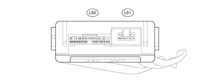
NO. 2 MULTIPLEX NETWORK BODY ECU (w/ Washer Nozzle Heater System)
-
Disconnect the L50 and L51 No. 2 multiplex network body ECU connectors.
-
Measure the voltage and resistance according to the value(s) in the table below.
Terminal No. (Symbol) Wiring Color Terminal Description Condition Specified Condition L50-14 (BECU) - Body ground R - Body ground Power source circuit Always 11 to 14 V L50-13 (SIG) - Body ground G - Body ground IG signal circuit Ignition switch ON 11 to 14 V Ignition switch off Below 1 V L50-7 (GND) - Body ground W-B - Body ground Ground circuit Always Below 1 Ω -
Reconnect the L50 and L51 No. 2 multiplex network body ECU connectors.
-
Measure the voltage according to the value(s) in the table below.
Terminal No. (Symbol) Wiring Color Terminal Description Condition Specified Condition L50-25 (WHTR) - Body ground GR - Body ground Washer nozzle heater signal circuit Ignition switch ON, ambient temperature 6°C (42°F) or higher 11 to 14 V Ignition switch ON, ambient temperature 5°C (41°F) or less Below 1 V
-