WIPER AND WASHER SYSTEM (w/ Rain Sensor) Wiper and Washer Switch Circuit
DESCRIPTION
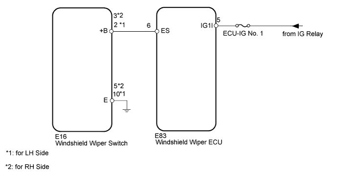
This circuit provides power to operate the windshield wiper switch. The manual operation signals are sent to the windshield wiper ECU.
WIRING DIAGRAM
INSPECTION PROCEDURE
PROCEDURE
-
INSPECT FUSE (ECU-IG No. 1)
-
Remove the ECU-IG No. 1 fuse from the cowl side junction block LH.
-
Measure the resistance according to the value(s) in the table below.
Standard Resistance Tester Connection Condition Specified Condition ECU-IG No. 1 fuse Always Below 1 Ω
NG 
REPLACE FUSE
OK 
-
-
READ VALUE USING INTELLIGENT TESTER (WINDSHIELD WIPER SWITCH)
-
Check the Data List for proper functioning of the windshield wiper switch.
Combination Switch Tester Display Measurement Item/Range Normal Condition Diagnostic Note F Wiper LO SW Front wiper LO switch / ON or OFF ON: Front wiper switch in LO
OFF: Front wiper switch not in LO
- F Wiper HI SW Front wiper HI switch / ON or OFF ON: Front wiper switch in HI
OFF: Front wiper switch not in HI
- F Wiper AUTO SW Front wiper AUTO switch / ON or OFF ON: Front wiper switch in AUTO
OFF: Front wiper switch not in AUTO
- F Wiper MIST SW Front wiper MIST switch / ON or OFF ON: Front wiper switch in MIST
OFF: Front wiper switch not in MIST
- F Washer SW Front washer switch / ON or OFF ON: Front washer switch on
OFF: Front washer switch off
- OK The display is as specified in the normal condition.
NG 
CHECK HARNESS AND CONNECTOR (WINDSHIELD WIPER SWITCH - BATTERY AND BODY GROUND) Click here
OK 
PROCEED TO NEXT SUSPECTED AREA SHOWN IN PROBLEM SYMPTOMS TABLE Click here
-
-
CHECK HARNESS AND CONNECTOR (WINDSHIELD WIPER SWITCH - BATTERY AND BODY GROUND)
-
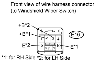
Disconnect the E16 switch connector.
-
Measure the voltage according to the value(s) in the table below.
Standard Voltage for LH Side Tester Connection Switch Condition Specified Condition E16-2 (+B) - Body ground Engine switch on (IG) 11 to 14 V E16-2 (+B) - Body ground Engine switch off Below 1 V for RH Side Tester Connection Switch Condition Specified Condition E16-3 (+B) - Body ground Engine switch on (IG) 11 to 14 V E16-3 (B) - Body ground Engine switch off Below 1 V -
Measure the resistance according to the value(s) in the table below.
Standard Resistance for LH Side Tester Connection Condition Specified Condition E16-10 (E) - Body ground Always Below 1 Ω for RH Side Tester Connection Condition Specified Condition E16-5 (E) - Body ground Always Below 1 Ω
NG
REPAIR OR REPLACE HARNESS OR CONNECTOR
OK
REPLACE WINDSHIELD WIPER SWITCH ASSEMBLY Click here
-