OUTER MIRROR SWITCH INSPECTION

-
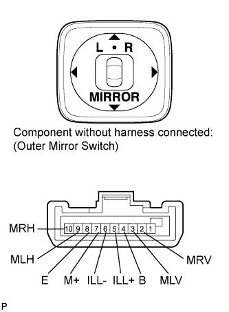
INSPECT OUTER MIRROR SWITCH ASSEMBLY (w/o Retract Mirror)
-
Inspect the outer mirror switch assembly.
-
Select "L" on the left/right adjustment switch.
-
Measure the resistance according to the value(s) in the table below.
Standard Resistance Tester Connection Condition Specified Condition 3 (MLV) - 4 (B)
7 (M+) - 8 (E)
Up Pressed Below 1 Ω Not pressed 10 kΩ or higher 3 (MLV) - 8 (E)
7 (M+) - 4 (B)
Down Pressed Below 1 Ω Not pressed 10 kΩ or higher 9 (MLH) - 4 (B)
7 (M+) - 8 (E)
Left Pressed Below 1 Ω Not pressed 10 kΩ or higher 9 (MLH) - 8 (E)
7 (M+) - 4 (B)
Right Pressed Below 1 Ω Not pressed 10 kΩ or higher If the result is not as specified, replace the outer mirror switch assembly.
-
Select "R" on the left/right adjustment switch.
-
Measure the resistance according to the value(s) in the table below.
Standard Resistance Tester Connection Condition Specified Condition 2 (MRV) - 4 (B)
7 (M+) - 8 (E)
Up Pressed Below 1 Ω Not pressed 10 kΩ or higher 2 (MRV) - 8 (E)
7 (M+) - 4 (B)
Down Pressed Below 1 Ω Not pressed 10 kΩ or higher 10 (MRH) - 4 (B)
7 (M+) - 8 (E)
Left Pressed Below 1 Ω Not pressed 10 kΩ or higher 10 (MRH) - 8 (E)
7 (M+) - 4 (B)
Right Pressed Below 1 Ω Not pressed 10 kΩ or higher If the result is not as specified, replace the outer mirror switch assembly.
-
-
Inspect the switch illumination.
-
Apply battery voltage between the terminals of the light, and check the operation of the light.
OK Measurement Condition Specified Condition Battery positive (+) → Terminal 5 (ILL+)
Battery negative (-) → Terminal 6 (ILL-)
Light comes on If the result is not as specified, replace the outer mirror switch assembly.
-
-
-
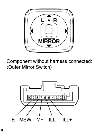
INSPECT OUTER MIRROR SWITCH ASSEMBLY (w/ Retract Mirror)
-
Inspect the outer mirror switch assembly.
-
Select "L" on the left/right adjustment switch.
-
Measure the resistance according to the value(s) in the table below.
Standard Resistance Tester Connection Switch Condition Specified Condition 8 (MSW) - 9 (E) L switch L position 10 kΩ or higher Neutral position 10 kΩ or higher 7 (M+) - 9 (E) Up Pressed 95 to 105 Ω Not pressed 10 kΩ or higher 7 (M+) - 9 (E) Down Pressed 446 to 493 Ω Not pressed 10 kΩ or higher 7 (M+) - 9 (E) Left Pressed 760 to 840 Ω Not pressed 10 kΩ or higher 7 (M+) - 9 (E) Right Pressed 237 to 262 Ω Not pressed 10 kΩ or higher If the result is not as specified, replace the outer mirror switch assembly.
-
Select "R" on the left/right adjustment switch.
-
Measure the resistance according to the value(s) in the table below.
Standard Resistance Tester Connection Switch Condition Specified Condition 8 (MSW) - 9 (E) R switch R position Below 1 Ω Neutral position 10 kΩ or higher 7 (M+) - 9 (E) Up Pressed 95 to 105 Ω Not pressed 10 kΩ or higher 7 (M+) - 9 (E) Down Pressed 446 to 493 Ω Not pressed 10 kΩ or higher 7 (M+) - 9 (E) Left Pressed 760 to 840 Ω Not pressed 10 kΩ or higher 7 (M+) - 9 (E) Right Pressed 237 to 262 Ω Not pressed 10 kΩ or higher If the result is not as specified, replace the outer mirror switch assembly.
-
-
Inspect the switch illumination.
-
Apply battery voltage between the terminals of the light, and check the operation of the light.
OK Measurement Condition Specified Condition Battery positive (+) → Terminal 5 (ILL+)
Battery negative (-) → Terminal 6 (ILL-)
Light comes on If the result is not as specified, replace the outer mirror switch assembly.
-
-
-
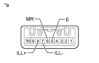
INSPECT RETRACTABLE OUTER MIRROR SWITCH (w/ Retract Mirror)
-
Inspect the retractable outer mirror switch.
-
Measure the resistance according to the value(s) in the table below.
Standard Resistance Tester Connection Switch Condition Specified Condition 5 (E) - 6 (MR) Pressed
(Retracts)
Below 1 Ω Not pressed 10 kΩ or higher If the result is not as specified, replace the retractable outer mirror switch.
-
-
Inspect the switch illumination.
-
Apply battery voltage between the terminals of the light, and check the operation of the light.
OK Measurement Condition Specified Condition Battery positive (+) → Terminal 8 (ILL+)
Battery negative (-) → Terminal 7 (ILL-)
Light comes on If the result is not as specified, replace the retractable outer mirror switch.
-
-